EMI connector ferrule and assembly combination therewith

a technology of emi connectors and ferrules, which is applied in the direction of securing/insulating coupling contact members, coupling device connections, and connections effected by permanent deformation, etc., can solve the problems of complex assembly process and inability to remove sleeves, and achieves convenient assembling/disassembly, economics, and otherwise reliable connection

Active Publication Date: 2013-09-24
FEDERAL MOGUL POWERTAIN LLC
View PDF21 Cites 4 Cited by
  • Summary
  • Abstract
  • Description
  • Claims
  • Application Information

AI Technical Summary

Benefits of technology

[0006]A ferrule and assembly therewith constructed in accordance with the invention provides an economical, easy to assemble / disassemble, watertight, and otherwise reliable connection between a protective textile sleeve and an electrical connector, while also providing a reliable ground path between the textile sleeve and the electrical connector.

Problems solved by technology

Unfortunately, the connection between the sleeve and the ferrule is typically located within the electrical connector, and thus, the assembly process is complicated and the sleeve can not be removed from the wires during service without first having to remove the ferrule from the electrical connector.

Method used


Image

  • EMI connector ferrule and assembly combination therewith
  • EMI connector ferrule and assembly combination therewith
  • EMI connector ferrule and assembly combination therewith

Examples


Embodiment Construction

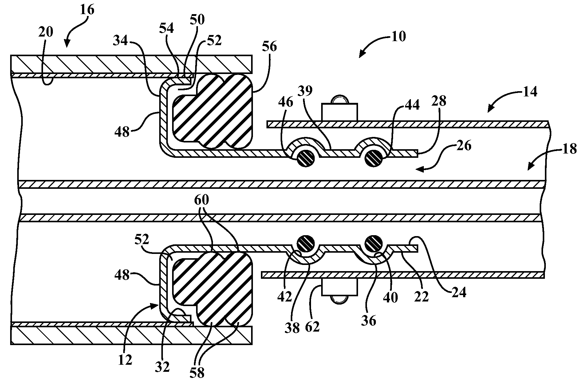
[0015]Referring in more detail to the drawings, FIGS. 1 (partially assembled) and 1A (fully assembled) illustrate a ferrule assembly 10 constructed in accordance with one aspect of the invention, wherein the ferrule assembly 10 includes at least a ferrule 12, constructed in accordance with another aspect of the invention, an electrically conductive textile sleeve 14, and an electrical connector 16. The textile sleeve 16 can be provided having any suitable length to provide protection to an elongate electrical member 18, whether a single electrical cable, bundled wire harness, or otherwise, extending therethrough and having any suitable diameter. Further, the textile sleeve 16 can be constructed having a circumferentially closes or open woven, knit or braided yarn structure, wherein the conductive aspect can be provided via electrically conductive yarns, coatings, films, foil, or otherwise. In addition, the conductive aspect of the electrical connector 16 can be provided via a separa...


PUM


Abstract

A ferrule configured to couple a textile sleeve to an electrical has a cylindrical wall with an inner surface providing a cavity sized for receipt of an elongate electrical member therethrough. The cylindrical wall extends between a first end configured for attachment within a cavity of the textile sleeve and a second end having a radially outwardly extending annular rim configured for attachment to the electrical connector. The cylindrical wall has at least one radially outwardly extending annular bead adjacent the first end with the annular bead providing a radially inwardly facing annular pocket. At least one seal member is disposed in the cavity for sealed abutment with the inner surface and the elongate electrical member.

Description

CROSS-REFERENCE TO RELATED APPLICATION[0001]This application claims the benefit of U.S. Provisional Application Ser. No. 61 / 355,291, filed Jun. 16, 2010, which is incorporated herein by reference in its entirety.BACKGROUND OF THE INVENTION[0002]1. Technical Field[0003]This invention relates generally to electrical connectors and, more particularly, to connector ferrules configured to couple and ground a protective sleeve to and electrical connector.[0004]2. Related Art[0005]It is known to protect elongate wires with metallic protective sleeves to provide a shield against electromagnetic interference (EMI). It is further known to ground the protective sleeve via a ferrule to an upstream metal electrical connector. Unfortunately, the connection between the sleeve and the ferrule is typically located within the electrical connector, and thus, the assembly process is complicated and the sleeve can not be removed from the wires during service without first having to remove the ferrule fr...

Claims


Application Information

Patent Timeline
Patent Type & Authority Patents(United States)
IPC IPC(8): H01R13/40
CPCH01R4/20H01R13/5219H01R13/5202H01R4/203H01R4/206H01R13/52H01R13/5205H01R13/5208
Inventor HARRIS, DAVID A.
Owner FEDERAL MOGUL POWERTAIN LLC
Why Eureka
Try Eureka