Stand tube of a bicycle

a technology of stand tube and bicycle, which is applied in the direction of steering device, medical science, animal teeth treatment, etc., can solve the problems of inability to adjust the front tube to the stand tube in many different orientations, hurt the users, and the c shape cannot provide an effective pressing force, etc., and achieve the effect of firm structur

Active Publication Date: 2008-10-21
CHEN CHAO HU
View PDF9 Cites 4 Cited by
  • Summary
  • Abstract
  • Description
  • Claims
  • Application Information

AI Technical Summary

Benefits of technology

[0010]Accordingly, the primary object of the present invention is to provide a stand tube of a bicycle, wherein the round portion is received into the U shape ear. The pivotal unit serves to connect the round portion and the U shape ear so as to have a firm structure.
[0011]Furthermore, in the present invention, the trenches of the pivotal unit are engaged with the ribs of the round portion so as to form a further firm structure of the present invention to prevent the deformation of the structure.

Problems solved by technology

However in this prior art, the front tube is not adjustable to the stand tube in many different orientations.
If the structure is used for a long time, the angled ends will release, while the user is seldom to find this phenomenon and thus it will hurt the users.
Moreover if the screw cannot effectively lock the C shape mouth, the C shape cannot provide an effective pressing force and thus gaps generate.
This will induce some dangerous conditions when the bicycle moves forwards.
It is possible that the bicycle is out of control.

Method used


Image

  • Stand tube of a bicycle
  • Stand tube of a bicycle
  • Stand tube of a bicycle

Examples


Embodiment Construction

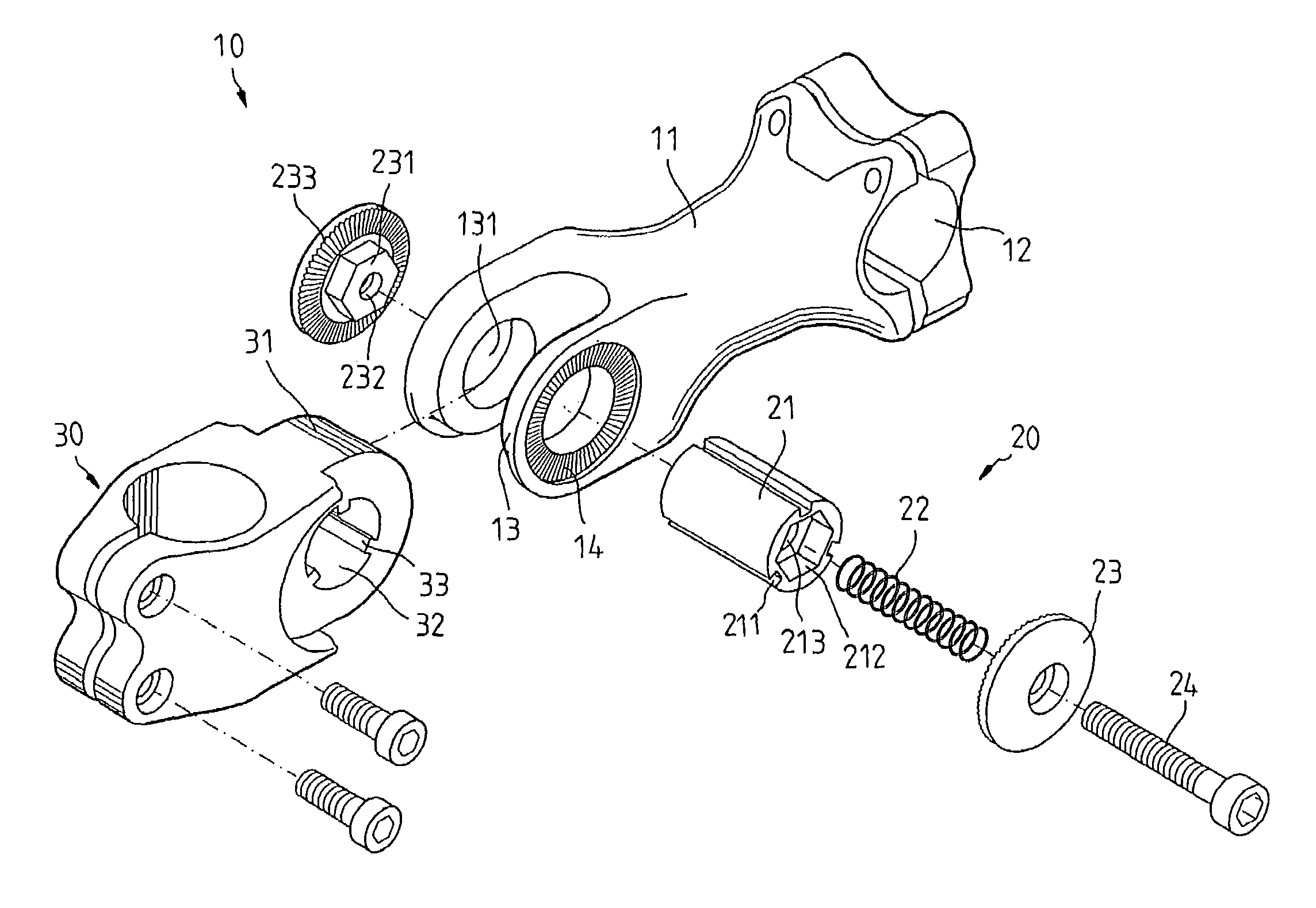
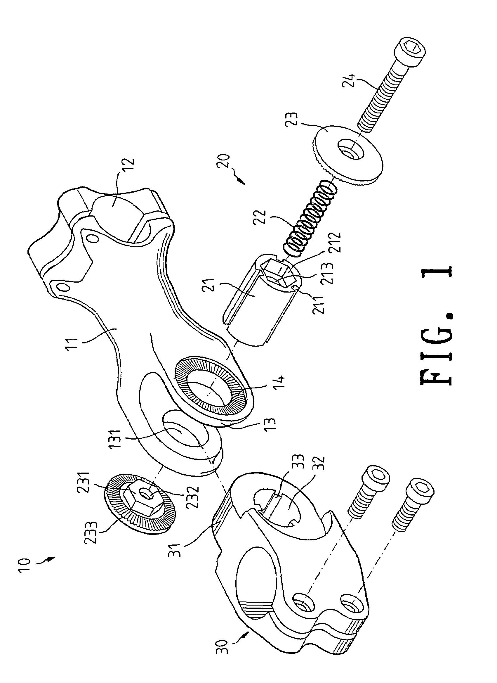
[0025]In order that those skilled in the art can further understand the present invention, a description will be provided in the following in details. However, these descriptions and the appended drawings are only used to cause those skilled in the art to understand the objects, features, and characteristics of the present invention, but not to be used to confine the scope and spirit of the present invention defined in the appended claims. Referring to FIG. 1, the structure of the present invention is illustrated. The stand tube 10 of a bicycle of present invention has the following elements.

[0026]A body 11 is included. One end of the body 11 is formed with a U shape ear 13 having two legs. Each leg of the U shape ear 13 has a pivotal hole 131. An outer side of each pivotal hole 131 has a teeth portion 14. Another end of the stand tube 10 is installed with a retaining portion 12.

[0027]A head 30 has one end formed with a round portion 31. The round portion 31 has a transversal penetr...


PUM


Abstract

A stand tube of a bicycle comprises a body; one end of the body formed with a U shape ear; each leg of the U shape ear having a pivotal hole; a head having one end formed with a round portion; the round portion having a transversal penetrating hole; a buckling unit having a pivotal unit; a receiving hole penetrating through the buckling unit; the buckling unit passing through the two pivotal holes and the penetrating hole; two buckles; one surface of the buckle being protruded with a protrusion; and a screw unit received in the receiving hole of the pivotal unit; the teeth of two buckles being then engaged to the teeth portion of the U shape ear and the two protrusion being received into the pivotal hole. By above assembly, the stand tube of a bicycle has a rigid and firm structure.

Description

FIELD OF THE INVENTION[0001]The present invention relates to bicycle parts, and in particular to a stand tube of a bicycle which has a rigid and firm structure.BACKGROUND OF THE INVENTION[0002]In the prior art stand tube of a bicycle, a front tube is connected to a stand tube. However in this prior art, the front tube is not adjustable to the stand tube in many different orientations.[0003]In one prior art, the Taiwan Patent No. 570010, an improvement structure is disclosed.[0004]In the prior art, a straight retainer and a transversal rod are used. One side of the straight retainer has a C shape mouth. A slit is formed in an opening of the mouth. A center of the mouth is hollowed. Two sides of the hollow portion are formed with angled holes. One end of the transversal rod has a slot for mounting the mouth. Two sides of the slot are wings. An outer end of the wing has a teeth surface for adhering a first block and a second block which have teeth rings. Each teeth ring has an angled e...

Claims


Application Information

Patent Timeline
Patent Type & Authority Patents(United States)
IPC IPC(8): B62K21/12
CPCB62K21/16Y10T74/20822
Inventor CHEN, CHAO-HU
Owner CHEN CHAO HU
Why Eureka
Try Eureka