
Flow force compensated sleeve valve

a technology of flow force and sleeve valve, which is applied in the field of valves, can solve the problems of not being easily actuated, adversely affected, and exerting significant force on the movable sleeve, and achieves the effects of improving fluid output, high precision and efficiency, and improving fluid outpu

Inactive Publication Date: 2008-10-21
SARCOS LC
View PDF33 Cites 8 Cited by
  • Summary
  • Abstract
  • Description
  • Claims
  • Application Information

AI Technical Summary

Benefits of technology

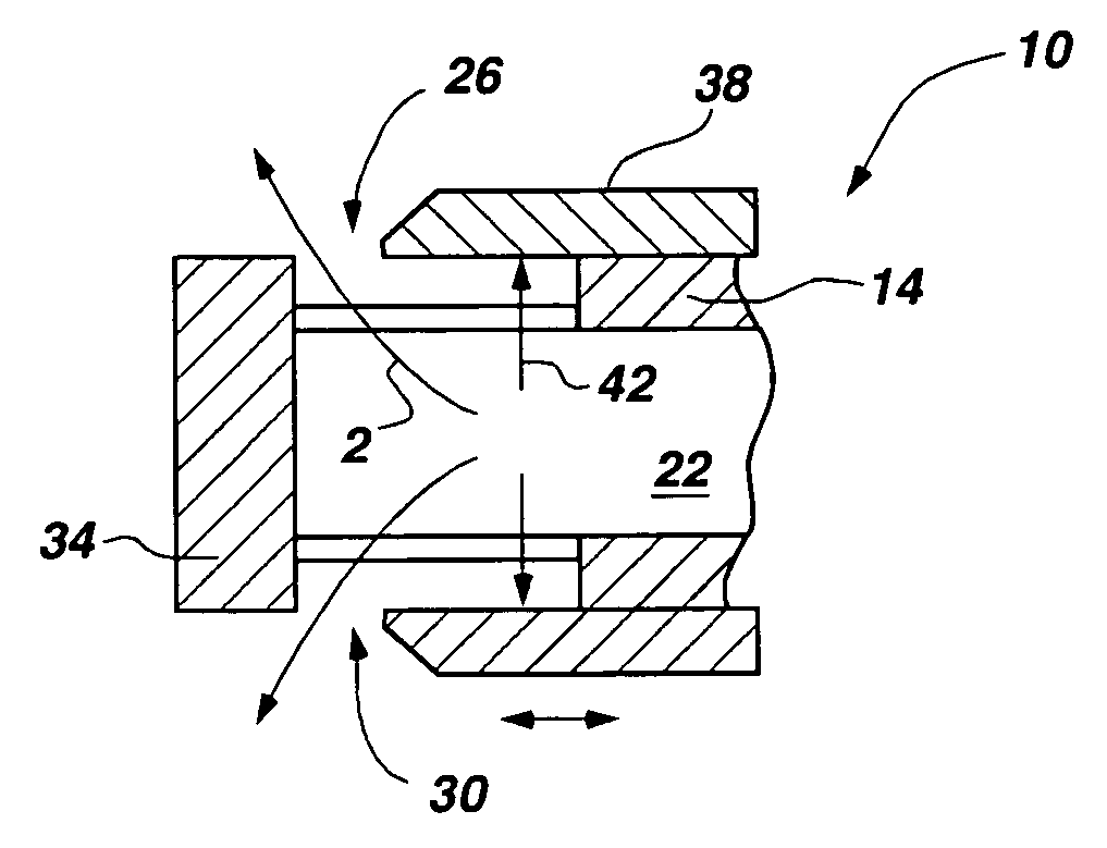
[0010]It is another object of some of the exemplary embodiments of the present invention to provide a sleeve valve where the forces required to actuate or displace the movable sleeve are substantially unaffected by the fluid pressures acting within the valve body.
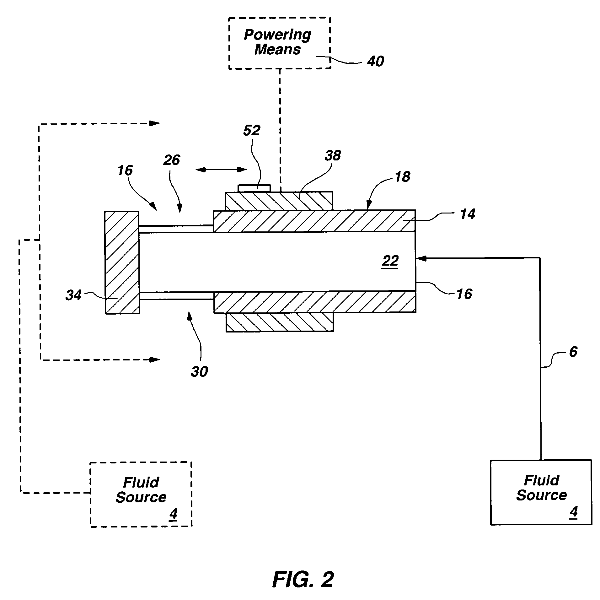
[0026]Another exemplary system in which the present invention sleeve valve may be utilized is within a decorative water delivery system. As such, the present invention further features a unique decorative water delivery system comprising at least one inlet for receiving fluid from a fluid source; at least one sleeve valve in fluid connection with the inlet; means for actuating the sleeve; and means for generating an artistic fluid emission. The sleeve valve comprises elements of any of the embodiments discussed above, thus allowing the fluid to be delivered in a highly precise and efficient manner.

Problems solved by technology

As a drawback to being used in such pressurized environments, however, the fluid pressures existing within the sleeve valve are capable of exerting significant forces on the movable sleeve, particularly if the movable sleeve is supported by one or more seats.
Thus, sleeve valves often comprise a movable sleeve that is not easily actuated and that is adversely affected by the fluid pressures existing within the sleeve valve.
Similarly, because of the fluid forces accompanying any type of forced fluid flow, manually operated sleeve valves are limited in their applications in that only low pressure fluid flows may be accepted or received therein.
A high pressure fluid flow would either bind the movable sleeve so that it cannot move, or significantly hinder its ability to move as a result of the forces acting upon the movable sleeve contributing to its resistance to any displacement or actuation.

Method used


Image

  • Flow force compensated sleeve valve
  • Flow force compensated sleeve valve
  • Flow force compensated sleeve valve

Examples


Embodiment Construction

[0044]The following detailed description of exemplary embodiments of the invention makes reference to the accompanying drawings, which form a part hereof and in which are shown, by way of illustration, exemplary embodiments in which the invention may be practiced. While these exemplary embodiments are described in sufficient detail to enable those skilled in the art practice the invention, it should be understood that other embodiments may be realized and that various changes to the invention may be made without departing from the spirit and scope of the present invention. Thus, the following more detailed description of the embodiments of the present invention, as represented in FIGS. 1 through 11-B, is not intended to limit the scope of the invention, as claimed, but is presented for purposes of illustration only and not limitation to describe the features and characteristics of the present invention, to set forth the best mode of operation of the invention, and to sufficiently en...


PUM


Abstract

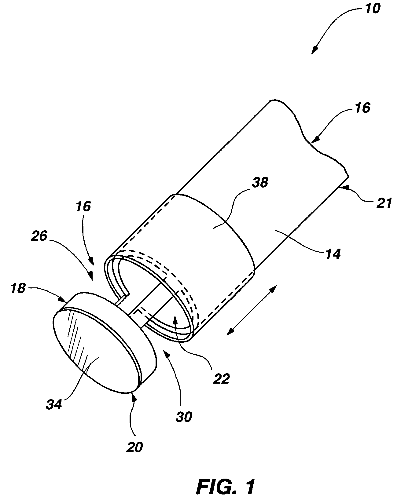
The present invention features a sleeve valve comprising an elongate body having an outer surface and including a lumen for receiving a fluid and an associated fluid pressure therein and for defining a flow path of the fluid; at least one fluid flow port formed through the outer surface that is in fluid connection with the lumen; and a sleeve slidably disposed about the outer surface of the body and configured to displace across the fluid flow port to precisely regulate fluid emission through the fluid flow port. The sleeve and elongate body are operably related in a manner so as to provide some degree of fluid force compensation, such that the forces necessary to displace the sleeve across the fluid flow port are substantially unaffected by the fluid pressures acting within the body and at the fluid flow port. In other words, the fluid pressures do not substantially contribute to the resistance in the sleeve during actuation.

Description

[0001]This application claims priority to U.S. Provisional Application Ser. No. 60 / 633,249, filed Dec. 2, 2004 in the United States Patent and Trademark Office, and entitled, “Flow Force Compensated Sleeve Valve,” which application is incorporated by reference in its entirety herein.FIELD OF THE INVENTION[0002]The present invention relates to valves for specifically controlling the emission or flow of fluid. More particularly, the present invention relates to a sleeve valve or a slide valve configured to produce highly controlled fluid flow and to relieve the effect of fluid pressures existing within the sleeve on the forces required to actuate the sleeve.BACKGROUND OF THE INVENTION AND RELATED ART[0003]Slide valves or sleeve valves are widely known in the art and are used in many different applications to control the fluid flow within a particular environment. Although a variety of sleeve valve designs exist, each comprises a common component or element that exists in one form or a...

Claims


Application Information

Patent Timeline
Patent Type & Authority Patents(United States)
IPC IPC(8): F16K3/24
CPCF16K3/24
Inventor JACOBSEN, STEPHEN C.OLSEN, SHANEMORRISON, MICHAEL
Owner SARCOS LC
Learn More