Pad for electronic drum and electronic drum

a technology for electronic drums and pads, applied in the direction of electrophonic musical instruments, percussion musical instruments, musical instruments, etc., can solve the problems of damage due to striking and deterioration, poor striking feel, complicated structure, etc., and achieve good striking feel

Inactive Publication Date: 2008-10-21
YAMAHA CORP
View PDF45 Cites 22 Cited by
  • Summary
  • Abstract
  • Description
  • Claims
  • Application Information

AI Technical Summary

Benefits of technology

[0010]To solve the above problems of the prior art, the present invention has been made, and an object thereof is to provide a pad for an electronic drum concurrently having improved three characteristics of quietness, durability and good striking feel, and an electronic drum having the same.

Problems solved by technology

However, there arise problems such as damage due to striking, and deterioration due to ultraviolet light as well as moisture and oxygen in the air because of poor structural durability and chemical durability.
When using materials having low hardness, for example, rubbers containing a dienic double bond and thermoplastic elastomers containing plasticizers such as low molecular weight oil component, quietness is improved because of high impact absorption properties, however, there arise problems such as poor striking feel due to greasiness, damage due to striking and deterioration due to ultraviolet light as well as moisture and oxygen in the air.
Therefore, it is necessary to further use a plate for solid or a retaining ring so as to mechanically retain this pad on the substrate, resulting in a complicated structure.

Method used


Image

  • Pad for electronic drum and electronic drum
  • Pad for electronic drum and electronic drum

Examples


example 1

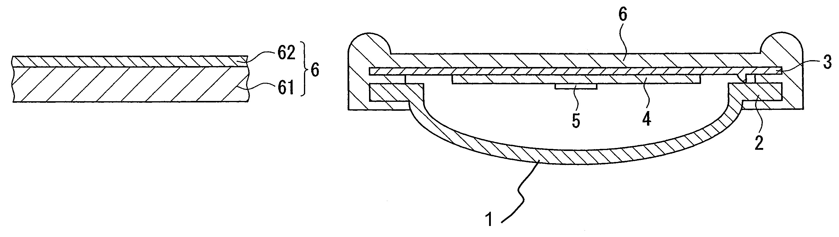
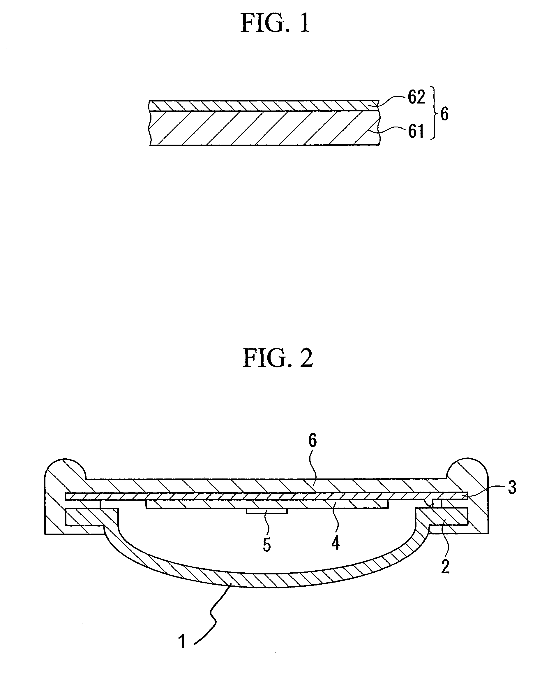
[0036]A pad 6 was produced by bonding a natural rubber (hardness: Shore A 60, thickness: 6 mm) as the body portion 61 with a polyethylene terephthalate film (thickness: 100 μm) as the surface layer portion 62 using an epoxy-based adhesive, and then an electronic drum having the structure shown in FIG. 1 was produced using the resulting pad 6.

[0037]In the resulting electronic drum comprising the pad 6, resiliency was improved, striking feel was improved, and furthermore a striking sound was satisfactorily dampened and good quietness was attained. Also it was made possible to minimize damage due to striking and deterioration of the body portion due to moisture and oxygen in an air.

example 2

[0038]A pad 6 was produced by applying a polyurethane coating composition to an olefinic thermoplastic elastomer (manufactured by JSR Co., Ltd., product number: Development TEL424, hardness: Shore A 20, thickness: 6 mm) serving as the body portion 61 to form a 60 μm thick coating film as the surface layer portion 62, and then an electronic drum was produced by using the resulting pad in the same manner as in Example 1.

[0039]In the resulting electronic drum comprising the pad 6, resiliency was improved and striking feel was improved and, furthermore, a striking sound was satisfactorily dampened and good quietness was attained. Also it was made possible to minimize damage due to striking and deterioration of the body portion due to moisture and oxygen in an air.

example 3

[0040]A pad 6 was produced by fixing a polypropylene film (thickness: 150 μm) as the surface layer portion 62 to an olefinic thermoplastic elastomer (manufactured by JSR Co., Ltd., product number: Development TEL424, hardness: Shore A 20, thickness: 6 mm) as the body portion 61 by means of an insert molding method, and then an electronic drum was produced by using the resulting pad in the same manner as in Example 1.

[0041]In the resulting electronic drum comprising the pad 6, resiliency was improved and striking feel was improved and, furthermore, a striking sound was satisfactorily dampened and good quietness was attained. Also it was made possible to minimize damage due to striking and deterioration of the body portion due to moisture and oxygen in an air.


PUM


Abstract

An electronic drum comprises a pad comprising a body portion made of a polymeric elastic material such as a rubber or a thermoplastic elastomer, and a surface layer portion which is bonded with the body portion so as to cover the body portion, the surface layer portion being made of a polymeric material having an elastic modulus of 0.5 to 20 GPa.

Description

BACKGROUND OF THE INVENTION[0001]1. Field of the Invention[0002]The present invention relates to a pad for an electronic drum in which a musical sound is obtained as an electronic sound by electronically converting a striking sound, and an electronic drum having the same.[0003]This application claims priority on Japanese Patent Application No. 2004-63888 filed on Mar. 8, 2004, the disclosure of which is incorporated herein by reference.[0004]2. Description of the Related Art[0005]This kind of electronic drum and pad for electronic drum serving as the striking face are described, for example, in Japanese Patent Application, First Publication No. Hei 9-244633 (corresponding to the U.S. Pat. No. 5,837,915).[0006]Examples of characteristics required of the material of such a pad for an electronic drum include quietness of a striking sound generated when the pad is struck by a stick, sufficient structural durability to endure long-term striking and intense striking, chemical durability ...

Claims


Application Information

Patent Timeline
Patent Type & Authority Patents(United States)
IPC IPC(8): G10D13/02G10H1/00G10H1/32
CPCG10D13/024G10D13/02G10D13/26
Inventor HIRAKU, TATSUYA
Owner YAMAHA CORP
Why Eureka
Try Eureka