Identifying optical fiber segments and determining characteristics of an optical device under test based on fiber segment scatter pattern data

a fiber segment and scatter pattern technology, applied in the field of optical measurements, can solve the problem that one cannot determine from simple ofdr or otdr measurements in which fiber a specific loss event occurred

Active Publication Date: 2008-10-21
INTUITIVE SURGICAL OPERATIONS INC
View PDF7 Cites 112 Cited by
  • Summary
  • Abstract
  • Description
  • Claims
  • Application Information

AI Technical Summary

Benefits of technology

[0003]Mixing between a reference signal and a data signal is often necessary to extract information about an optical device or network. A probe signal and a reference signal originating from the same source are typically mixed, resulting in fringes that can be detected and used to assess information about the device being probed. In interferometric sensing, a reference signal is mixed with a signal whose phase and / or amplitude is modified by a parameter to be measured. The mixing produces an interference signal, and the amplitude of the interference signal depends on how efficiently the two optical signals mix.
[0007]When couplers are used in an optical network, reflectometric interrogation from one side of a coupler produces a measurement in which the backscatter from the two output legs of the coupler is combined into a single trace as illustrated in FIG. 1. Although scattering events and losses can be identified, one cannot determine from simple OFDR or OTDR measurements in which fiber a specific loss event occurred. Without the ability to distinguish different branches of a network, it is possible to identify that there is a faulty optical component in an optical network that contains multiple fibers, but nonetheless cut the wrong fiber when trying to replace the faulty component. In this and other types of cases, knowledge of which individual fiber caused a loss event (rather than the general information that one of the fibers caused a loss event) would be very helpful in achieving a quick and efficient repair of the system.

Problems solved by technology

Although scattering events and losses can be identified, one cannot determine from simple OFDR or OTDR measurements in which fiber a specific loss event occurred.
Without the ability to distinguish different branches of a network, it is possible to identify that there is a faulty optical component in an optical network that contains multiple fibers, but nonetheless cut the wrong fiber when trying to replace the faulty component.

Method used


Image

  • Identifying optical fiber segments and determining characteristics of an optical device under test based on fiber segment scatter pattern data
  • Identifying optical fiber segments and determining characteristics of an optical device under test based on fiber segment scatter pattern data
  • Identifying optical fiber segments and determining characteristics of an optical device under test based on fiber segment scatter pattern data

Examples


Embodiment Construction

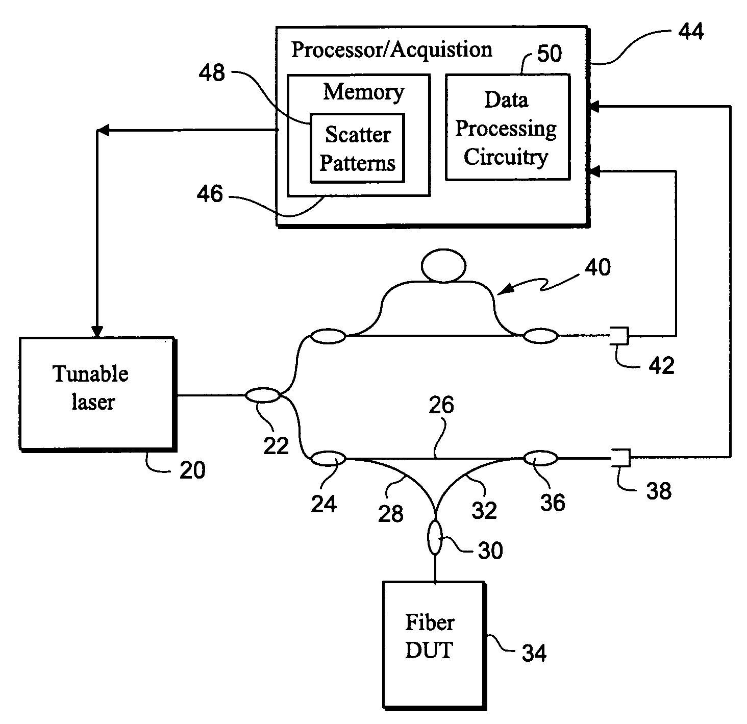
[0024]In the following description, for purposes of explanation and non-limitation, specific details are set forth, such as particular nodes, functional entities, techniques, protocols, standards, etc. in order to provide an understanding of the described technology. It will apparent to one skilled in the art that other embodiments may be practiced apart from the specific details disclosed below. In other instances, detailed descriptions of well-known methods, devices, techniques, etc. are omitted so as not to obscure the description with unnecessary detail. Individual function blocks are shown in the figures. Those skilled in the art will appreciate that the functions of those blocks may be implemented using individual hardware circuits, using software programs and data in conjunction with a suitably programmed microprocessor or general purpose computer, using applications specific integrated circuitry (ASIC), and / or using one or more digital signal processors (DSPs).
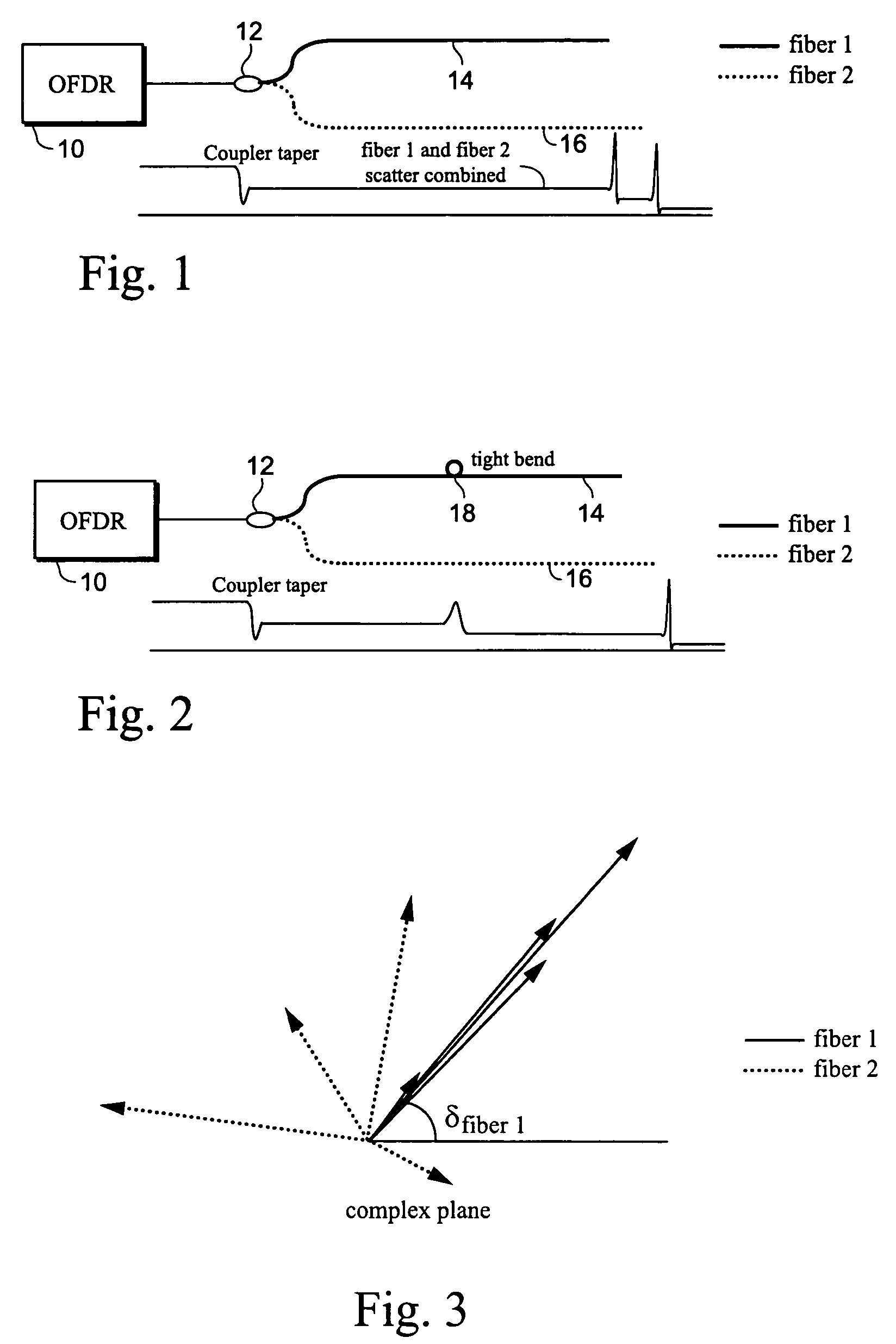
[0025]FIG. 1 i...


PUM

PropertyMeasurementUnit
wavelength rangeaaaaaaaaaa
Optical Frequency Domain Reflectometryaaaaaaaaaa

Abstract

Complex data is obtained from OFDR backscatter measurements for an optical device under test (DUT). That complex scatter pattern data may be used along with a previously-determined fiber segment pattern to identify the fiber segment within the DUT, even when the DUT is an optical network DUT that includes multiple fibers coupled to perform one or more functions. In other non-limiting example applications, the OFDR scatter pattern data can be used to identify where in the DUT a loss occurred and where in the DUT a temperature change occurred.

Description

CLAIM OF BENEFIT OF PROVISIONAL PATENT APPLICATION[0001]Priority is claimed from U.S. Provisional Patent Application No. 60 / 546,962, filed on Feb. 24, 2004. The contents of this provisional application are incorporated by reference.TECHNICAL FIELD[0002]The technical field relates to optical measurements, and more particularly, to advantageous new uses of Optical Frequency Domain Reflectometry (OFDR).BACKGROUND AND SUMMARY[0003]Mixing between a reference signal and a data signal is often necessary to extract information about an optical device or network. A probe signal and a reference signal originating from the same source are typically mixed, resulting in fringes that can be detected and used to assess information about the device being probed. In interferometric sensing, a reference signal is mixed with a signal whose phase and / or amplitude is modified by a parameter to be measured. The mixing produces an interference signal, and the amplitude of the interference signal depends o...

Claims


Application Information

Patent Timeline
Patent Type & Authority Patents(United States)
IPC IPC(8): G01N21/00G02B6/00G01M11/00
CPCG01M11/3172
Inventor FROGGATT, MARK EARLSOLLER, BRIAN JOSEPH
Owner INTUITIVE SURGICAL OPERATIONS INC
Why Eureka
Try Eureka