Electrical fitting with internal cable retainer

a technology of internal cable retainer and electrical fitting, which is applied in the direction of electrical equipment, substation/switching arrangement details, coupling device connections, etc., can solve the problems of mechanical complexity and relatively high production cost of electrical fitting, and achieve the effect of convenient cable or conduit insertion

Active Publication Date: 2008-10-28
ARLINGTON INDS
View PDF13 Cites 15 Cited by
  • Summary
  • Abstract
  • Description
  • Claims
  • Application Information

AI Technical Summary

Benefits of technology

[0012](4) The cable retaining tang is notched on both edges at its juncture with the ring, thereby enabling easier insertion of cables or conduit into the fitting.
[0013]These and other objects and advantages of the present invention will be better understood by reading the following description along with reference to the drawings.

Problems solved by technology

Although the prior art split ring adequately performed the function of gripping a cable, as a result of the multiple tangs, the electrical fitting was mechanically complex and relatively expensive to produce.

Method used


Image

  • Electrical fitting with internal cable retainer
  • Electrical fitting with internal cable retainer
  • Electrical fitting with internal cable retainer

Examples


first embodiment

[0058]Referring to FIGS. 5-7, the cylindrical panel-engaging ring 30 of the first embodiment is formed from a blank 48 as shown in FIG. 5 into a substantially cylindrical shape as shown in FIGS. 6 and 7. The panel-engaging ring 30 includes panel engagement tangs 50 and grounding tangs 52 bent outwards of the ring.

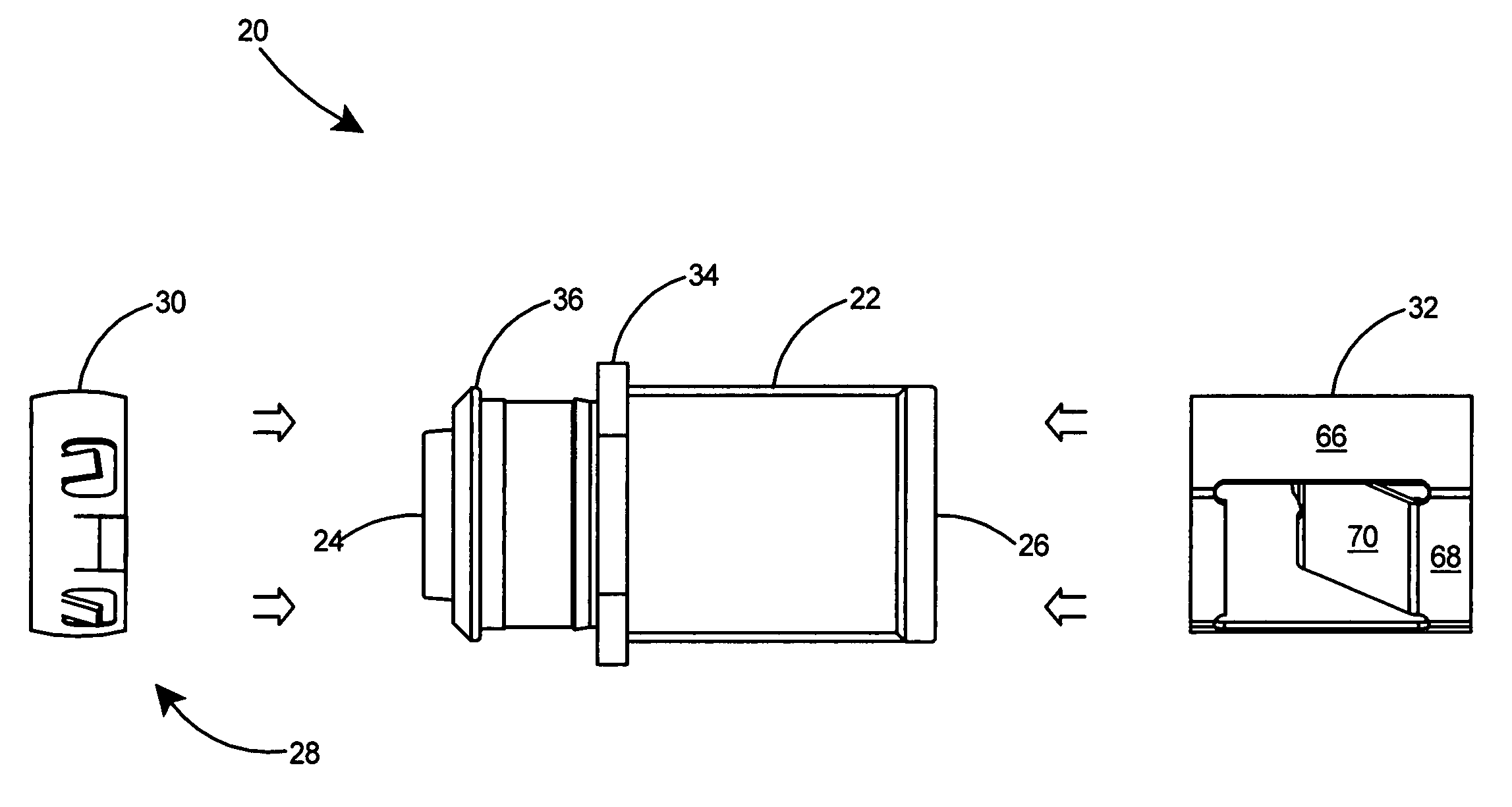
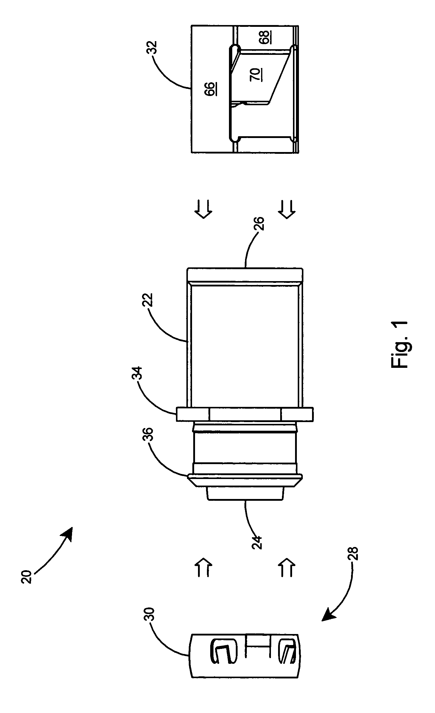
[0059]The main advantages of the present invention are realized from the arrangement of the cable retainer 32 as shown in FIGS. 8-14. As shown in FIG. 8, the cable retainer 32 is formed from a flat blank 54 of spring steel having two ends 56 and 58. The blank 54 includes bend lines 60 laterally across the blank 54 and separate bend lines 62, 63, and 64 longitudinally along the blank. The blank 54 of FIG. 8 will be formed into a substantially tubular body 66 as shown in FIGS. 9 and 10 but with a flat portion 68 formed between bend lines 60. A cable retaining tang 70 is formed by bending inward of the tubular body 66 at bend line 62 and a locking tang 72 formed by bending out...

second embodiment

[0071]Several advantages of the present invention are realized from the arrangement of the cable retainer 204 as shown in FIGS. 26-32. The second and preferred embodiment of the cable retainer 204 is formed from a flat blank 212 (see FIG. 26) of spring steel having two ends 56 and 58. The blank 212 includes bend lines 60 laterally across the blank 212, bend lines 62 and 63 longitudinally along the blank 212, and bend line 214 at an angle θ2 that is preferably between 10 and 20 degrees with respect to the edge 216 of the blank and most preferably at an angle of 15 degrees with respect to the edge 216 of the blank. The blank 212 of FIG. 26 will be formed into a substantially tubular body 222 as shown in FIGS. 27 and 28 but with a chord or flat portion 68 formed between bend lines 60. The cable retaining tang 208 is formed by bending inward of the tubular body 222 at bend line 62 and a locking tang 72 formed by bending outward of the tubular body 222 at bend line 63. The cable retainin...


PUM


Abstract

An electrical fitting with an improved arrangement on the trailing end for the quick connection of electrical cables. The fitting includes a connector body with a cavity in the trailing end and a cable retainer secured therein. The tubular cable retainer is constructed of spring steel and includes a flat portion and an arcuate portion. A single cable-retaining tang extends inwardly from the flat portion and includes notched edges at its juncture with the tubular body, thereby enhancing the resiliency of the tang. A wide cable-gripping surface on the cable-retaining tang enables secure gripping of an electrical cable as it is inserted within the trailing end of the fitting. End legs on the cable-retaining tang are at an angle with respect to the edge of the cable retainer thereby orienting the end legs with the grooves on an armored or similar electrical cable.

Description

[0001]This application is a Continuation-In-Part of U.S. patent application Ser. No. 11 / 707,582 filed Feb. 16, 2007 now U.S. Pat. No. 7,381,088 which is incorporated herein by reference in its entirety for all purposes.FIELD OF THE INVENTION[0002]This invention relates to fittings for connecting electrical cables to a panel and specifically to an electrical fitting having an improved arrangement on the trailing end for receiving an electrical cable or conduit.BACKGROUND OF THE INVENTION[0003]Electrical fittings are commonly used to connect electrical cables to electrical panels or boxes. In recent years, quick connect electrical fittings have become increasingly popular.[0004]Several prior art connectors have been proposed for the attachment of electrical cables or conduits to panels or electrical boxes. Some of these, such as that shown in U.S. Pat. No. 6,335,488 to Gretz, include a tubular body with a cavity on the trailing end and a cylindrical-shaped split ring that is inserted ...

Claims


Application Information

Patent Timeline
Patent Type & Authority Patents(United States)
IPC IPC(8): H01R13/73
CPCH02G3/0691
Inventor GRETZ, THOMAS J.
Owner ARLINGTON INDS
Why Eureka
Try Eureka