
Auto-injector

Active Publication Date: 2008-10-28
SHL MEDICAL AG
View PDF11 Cites 160 Cited by
  • Summary
  • Abstract
  • Description
  • Claims
  • Application Information

AI Technical Summary

Benefits of technology

[0008]The aim of the present invention is to provide an auto-injection device without the above mentioned drawbacks which is user-friendly, easy to use, with a high degree of safety and greatly reduces the risk of unintentional misfiring.
[0010]With an auto-injection device according to the present invention several advantages are obtained. The main activating means, which releases the spring means that performs the ejection of the needle and the injection of the medicament can not be operated unless the injector is actually pressed against the injection site. It is thus required to perform a “two-step” operation in order to inject the medicament. First the injector is pressed against the injection site, whereby the locking of the activator or firing button is released. After that the button may be pressed whereby the spring-loaded syringe is activated and the medicament is injected. This reduces the risk that the injector is misfired before it is placed on the appropriate and desired location because the activator cannot be depressed unless there is a pressure on the contact part of the injector.
[0011]The design is also so that if the injector is lifted again after pressing it against the injection site, if for example the patient wishes to use another site, the activator is again locked, i e the activator is always locked when the contact part of the injector is not under pressure. Further, the “two-step” operation can not be done in the opposite way, i e by first pressing the activator and then pressing the injector against the injection site, thereby further preventing accidental misfiring of the injector. Even so the injector according to the invention is simple to use and user-friendly. There is no need for removing safety caps or bending away safety pins in order to activate the injector, the patient just have to press the injector against the desired injection location.
[0012]In a preferred embodiment of the invention, the contact part is the needle cover, which completely covers the needle before use. Upon injection, the needle penetrates the needle cover. This enables the needle to be kept sterile before use. There is thus no need for removal of such covers before injection. When the injection cycle is almost completed, the spring-loaded needle cover is released from the housing so that it can be pushed out around the needle upon withdrawal of the injector from the injection site. The needle of the injector of the present invention is thus never exposed or visible to the patient, which enhances the safety of the device and also provides a comfort aspect to patients that do not like to see needles, such as children. When the cover is pushed out, it is locked in that position, thereby preventing the needle to becoming exposed by pushing the needle cover back into the injector.

Problems solved by technology

Further, the “two-step” operation can not be done in the opposite way, i e by first pressing the activator and then pressing the injector against the injection site, thereby further preventing accidental misfiring of the injector.

Method used


Image

  • Auto-injector
  • Auto-injector
  • Auto-injector

Examples


Embodiment Construction

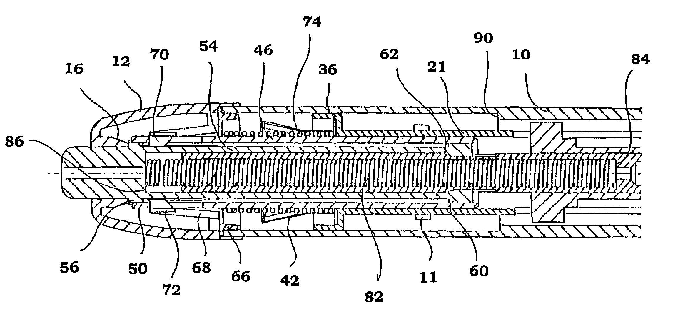
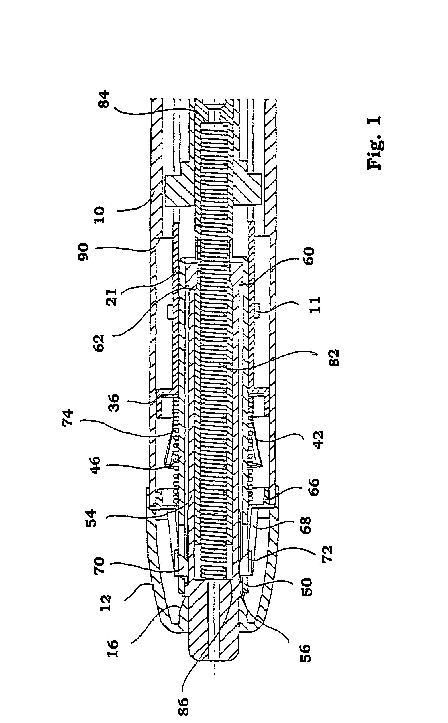
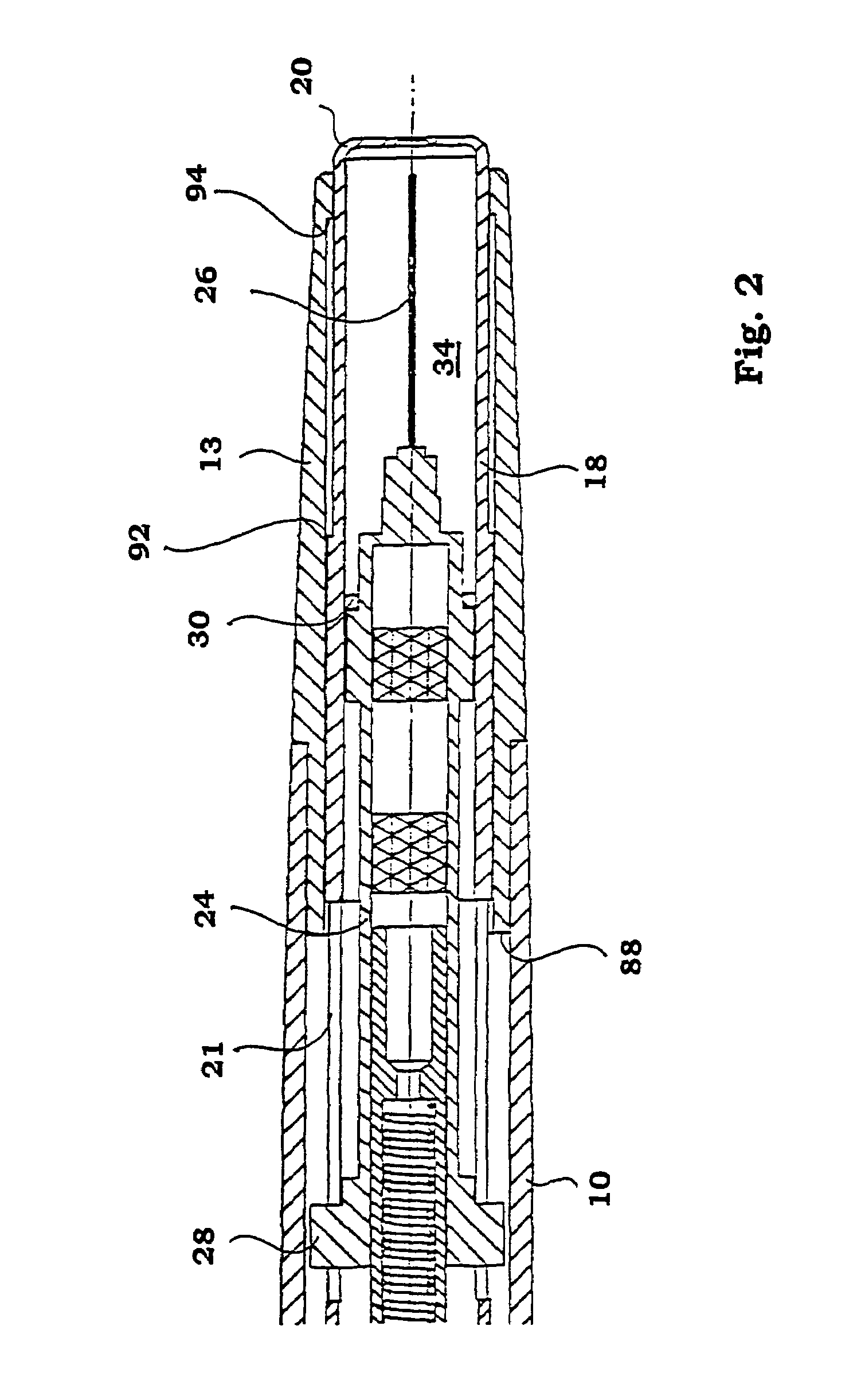
[0025]The injector according to a conceivable embodiment shown in the FIGS. 1-9 comprises an elongated generally tubular central housing 10 open at both ends. The central housing is provided with openings 11. One end of the housing is arranged with a front end piece 13 with a somewhat conical shape. The other end of the central housing is arranged with an end cap 12 attached to the housing. The end cap is provided with a tubular passage 14. The inner end of the tubular passage is arranged with conical surfaces 16. A tubular body 18, hereafter named needle cover, is slidably arranged in the front end piece and protruding a short distance from the end of the front end piece.

[0026]The end of the needle cover protruding from the front end piece is arranged with a closing end wall 20. Behind the needle cover, a tubular body 21, hereafter named front extension tube, is slidably arranged in the housing, where its front end is abutting the rear end of the needle cover. The front extension t...


PUM


Abstract

A device for auto-injection of a dose of medicament, comprises a housing arranged to contain a medicament container therein and a contact part intended to be applied against an injection site, a needle cover surrounding a needle arranged to the medicament container and extending at least the length of the needle, spring elements for, upon activation, pushing the needle past the end of the cover as well as operating the medicament container to supply the dose of medicament, first locking elements for locking the spring elements in a pressurized state, first activating elements for, upon manual operation, releasing the spring elements for injection. There is a second locking element capable of locking the first activating element and a second activating element, capable of releasing the second locking element when the contact part is exposed to pressure.

Description

TECHNICAL FIELD[0001]The present invention relates to an auto-injection device intended for injection of a dose of medicament, comprising a housing arranged to contain a syringe therein and comprising a contact part intended to be applied against an injection site, a needle cover surrounding the needle of the syringe, spring means capable of, upon activation, pushing the needle through the needle cover as well as injecting the dose of medicament, first locking means capable of locking said spring means in a pressurised state, and first activating means capable of, upon manual operation, releasing said spring means for injection.BACKGROUND OF THE INVENTION[0002]Automatically, or semi-automatically activated, injection devices have been on the market for many years. One of the first types was intended for war-times, which type was activated by merely pressing or slamming the injector against a body part thereby activating it. The main concern was to have the medicament injected as fas...

Claims


Application Information

Patent Timeline
IPC IPC(8): A61M5/20A61M5/32
CPCA61M5/2033A61M2005/206A61M2005/208
Inventor AMARK, MIKAELBERGENS, THOMAS
Owner SHL MEDICAL AG
Learn More