

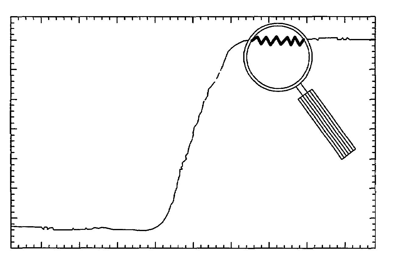
Instrument having a virtual magnifying glass for displaying magnified portions of a signal waveform
a virtual magnifying glass and signal waveform technology, applied in instruments, computing, drawing from basic elements, etc., can solve the problems of user loss of context of the magnified portion of the waveform in the original waveform, difficulty in visual examination, and inability to conveniently use cursor or marker functions, etc., to achieve the effect of improving the efficiency of instruments
- Summary
- Abstract
- Description
- Claims
- Application Information
AI Technical Summary
Benefits of technology
Problems solved by technology
Method used
Image

Examples
Embodiment Construction
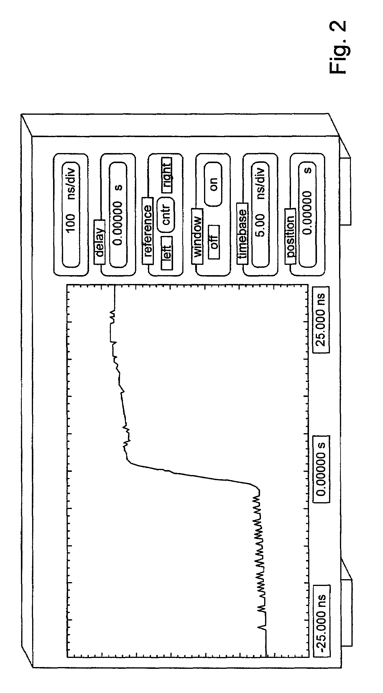
FIGS. 2 and 3—Exemplary Instruments
[0024]FIG. 2 illustrates one embodiment of a traditional, stand-alone instrument which may include the magnification features of the present invention. FIG. 3 illustrates one embodiment of a computer-based measurement system, also called a computer-based instrument or virtual instrumentation system, which may include the magnification features of the present invention. The present invention may be included in any of various types of systems which are used to display a signal waveform, such as instruments, computer systems, and other devices.
[0025]In one embodiment, the magnification features of the present invention are included in an instrument. As used herein, the term “instrument” is intended to include any of various devices which operate to collect data or information from an environment or unit under test and analyze and / or display this information to a user. Examples of various types of instruments include oscilloscopes, digital multimeters,...
PUM
 Abstract
Description
Claims
Application Information