Electronically-controlled hydraulically-actuated coupling

a hydraulically-actuated coupling, electric control technology, applied in the direction of non-mechanical actuated clutches, clutches, control devices, etc., can solve the problem of system cost prohibitive in some four-wheel drive applications

Active Publication Date: 2008-11-04
AMERICAN AXLE & MFG
View PDF23 Cites 14 Cited by
  • Summary
  • Abstract
  • Description
  • Claims
  • Application Information

AI Technical Summary

Problems solved by technology

For example, the size, weight and packaging requirements of the power transmission device may make such systems cost prohibitive in some four-wheel drive applications.

Method used


Image

  • Electronically-controlled hydraulically-actuated coupling
  • Electronically-controlled hydraulically-actuated coupling
  • Electronically-controlled hydraulically-actuated coupling

Examples


Embodiment Construction

[0013]The following description of the preferred embodiment(s) is merely exemplary in nature and is in no way intended to limit the invention, its application, or uses.

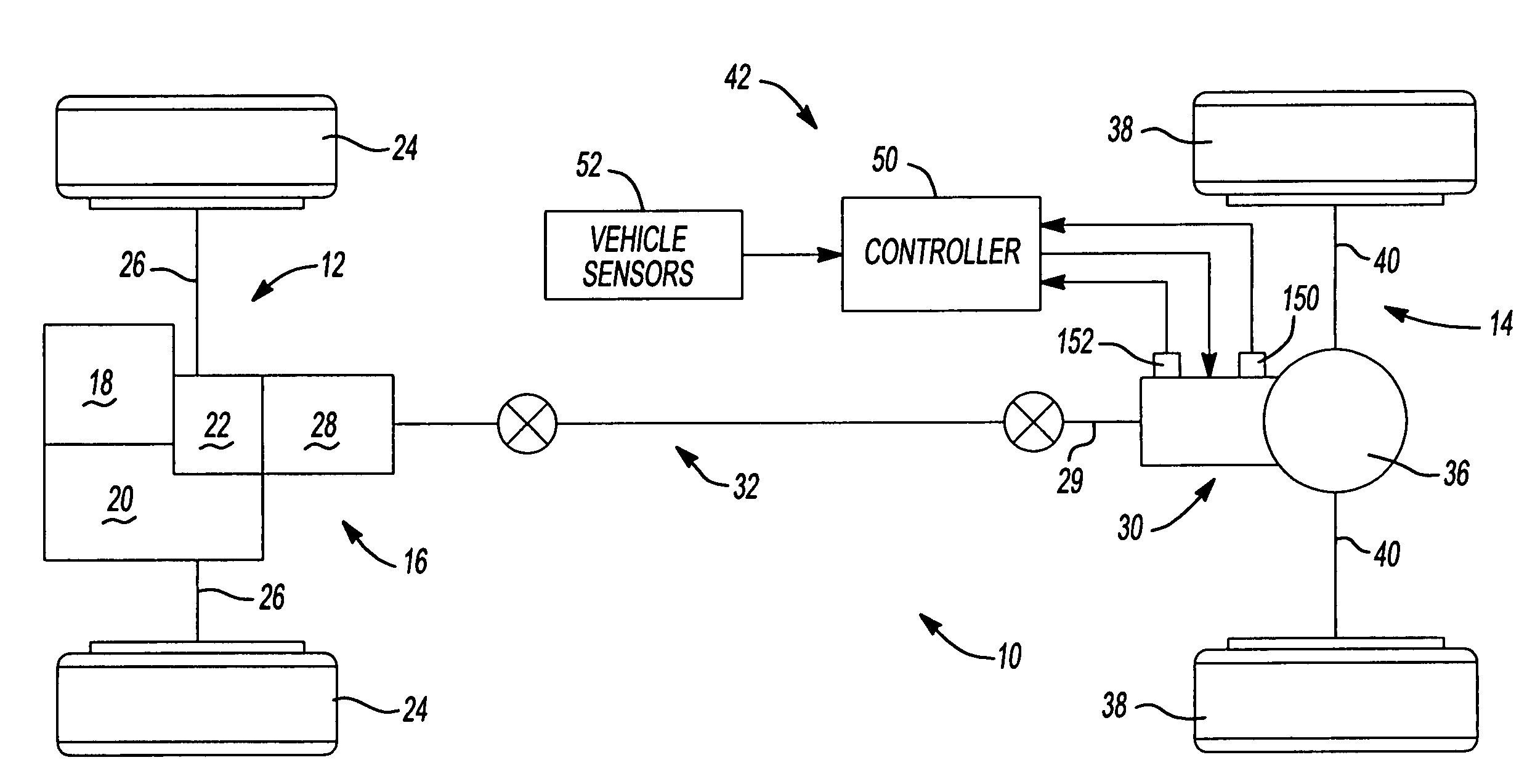
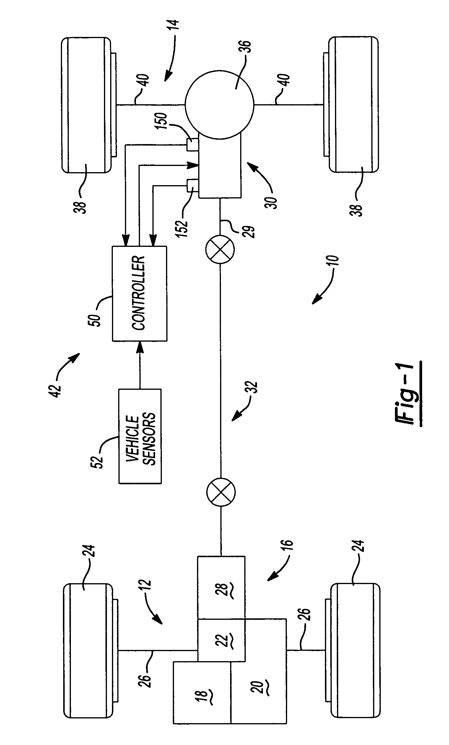
[0014]The present invention is directed to a power transmission device that may be adaptively controlled for modulating the torque transferred between a rotatable input member and a rotatable output member. The torque transfer mechanism may be useful within motor vehicle drivelines as a stand-alone device that may be easily incorporated between sections of propeller shafts, directly coupled to a driving axle assembly, or other in-line torque coupling applications. Accordingly, while the present invention is hereinafter described in association with a specific structural embodiment for use in a driveline application, it should be understood that the arrangement shown and described is merely intended to illustrate an exemplary embodiment of the present invention.

[0015]With reference to FIG. 1 of the drawings, a drive tr...


PUM


Abstract

A power transmission device includes a friction clutch operable to selectively transfer torque between an input member and an output member. An actuator is operable to provide an actuating force to the friction clutch. The actuator includes an electric motor having an output shaft drivingly coupled to a gerotor. The gerotor is operable to provide pressurized fluid to a piston acting on the friction clutch.

Description

BACKGROUND AND SUMMARY OF THE INVENTION[0001]The present invention relates generally to a power transmission device operable to selectively transfer torque between first and second sets of drivable wheels of a vehicle. More particularly, the present invention is directed to a power transmission device adapted for use in motor vehicle driveline applications having an actuator including an electric motor drivably coupled to a gerotor for providing pressurized fluid to a piston acting on a friction clutch.[0002]Due to increased demand for four-wheel drive vehicles, many power transmission systems are typically being incorporated into vehicle driveline applications for transferring drive torque to the wheels. Many vehicles include a power transmission device operably installed between the primary and secondary drivelines. Such power transmission devices are typically equipped with a torque transfer mechanism for selectively transferring drive torque from the primary driveline to the sec...

Claims


Application Information

Patent Timeline
Patent Type & Authority Patents(United States)
IPC IPC(8): F16D25/12F16D43/284F16D48/12
CPCB60K23/0808F16D25/0638F16D29/005F16D25/082
Inventor CAPITO, RUSSELL T.
Owner AMERICAN AXLE & MFG
Why Eureka
Try Eureka