Step apparatus

a technology of step apparatus and step position, which is applied in the direction of step arrangement, vehicle components, transportation and packaging, etc., can solve the problems of limited installation position large installation space of the drive unit, so as to achieve smooth and evenly guided

Inactive Publication Date: 2008-11-04
AISIN SEIKI KK
View PDF25 Cites 47 Cited by
  • Summary
  • Abstract
  • Description
  • Claims
  • Application Information

AI Technical Summary

Benefits of technology

[0015]In light of the above-described situation, an object of the present invention is to provide a step apparatus including a drive unit that can be installed in a small space and that can reduce the limit to the installation position thereof.

Problems solved by technology

Accordingly, the installation space for the drive unit is large.
Thus, the installation position of the drive unit is limited.
Accordingly, the installation space for the drive unit is large.
Thus, the installation position of the drive unit is limited.

Method used


Image

  • Step apparatus
  • Step apparatus
  • Step apparatus

Examples


Embodiment Construction

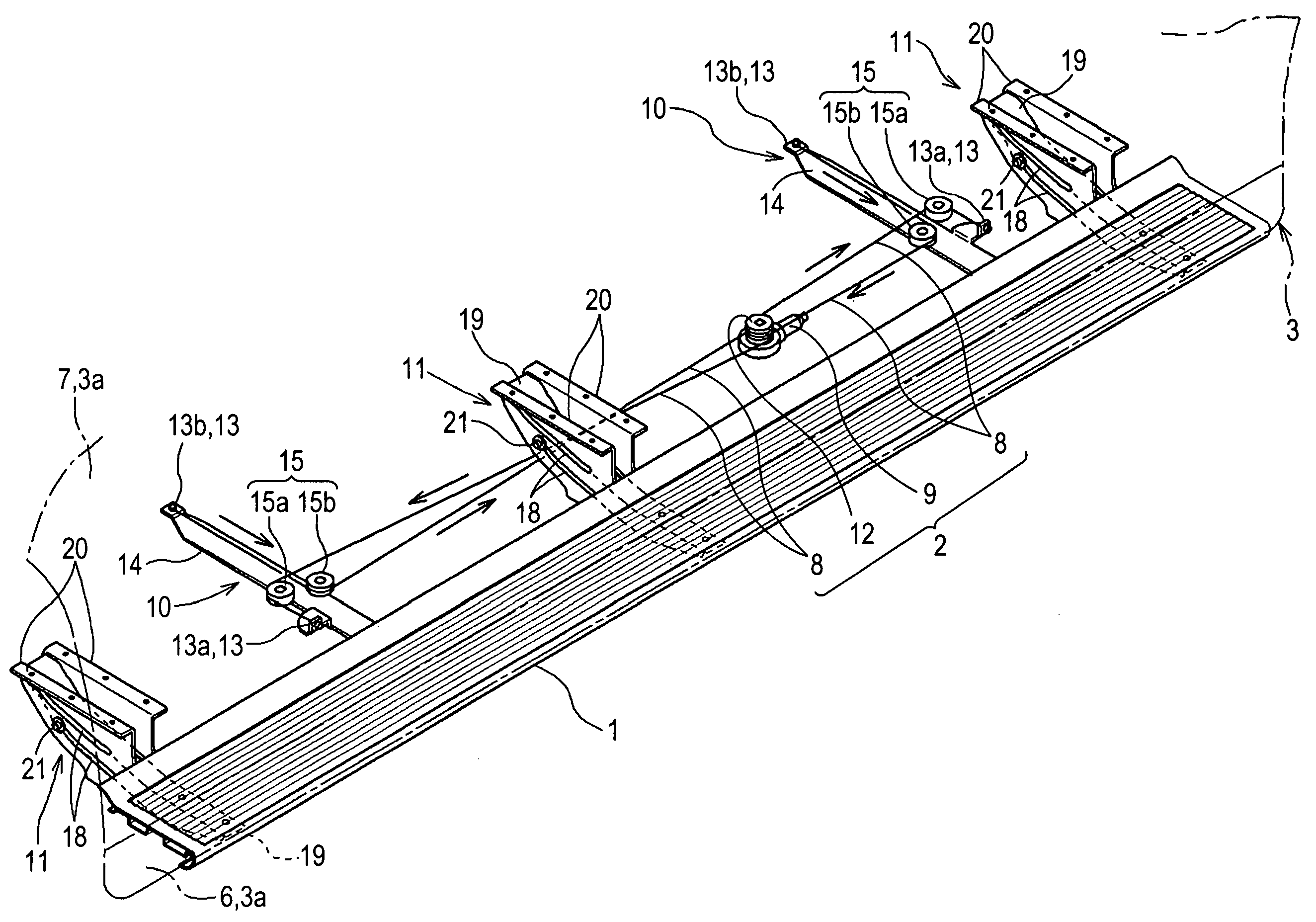
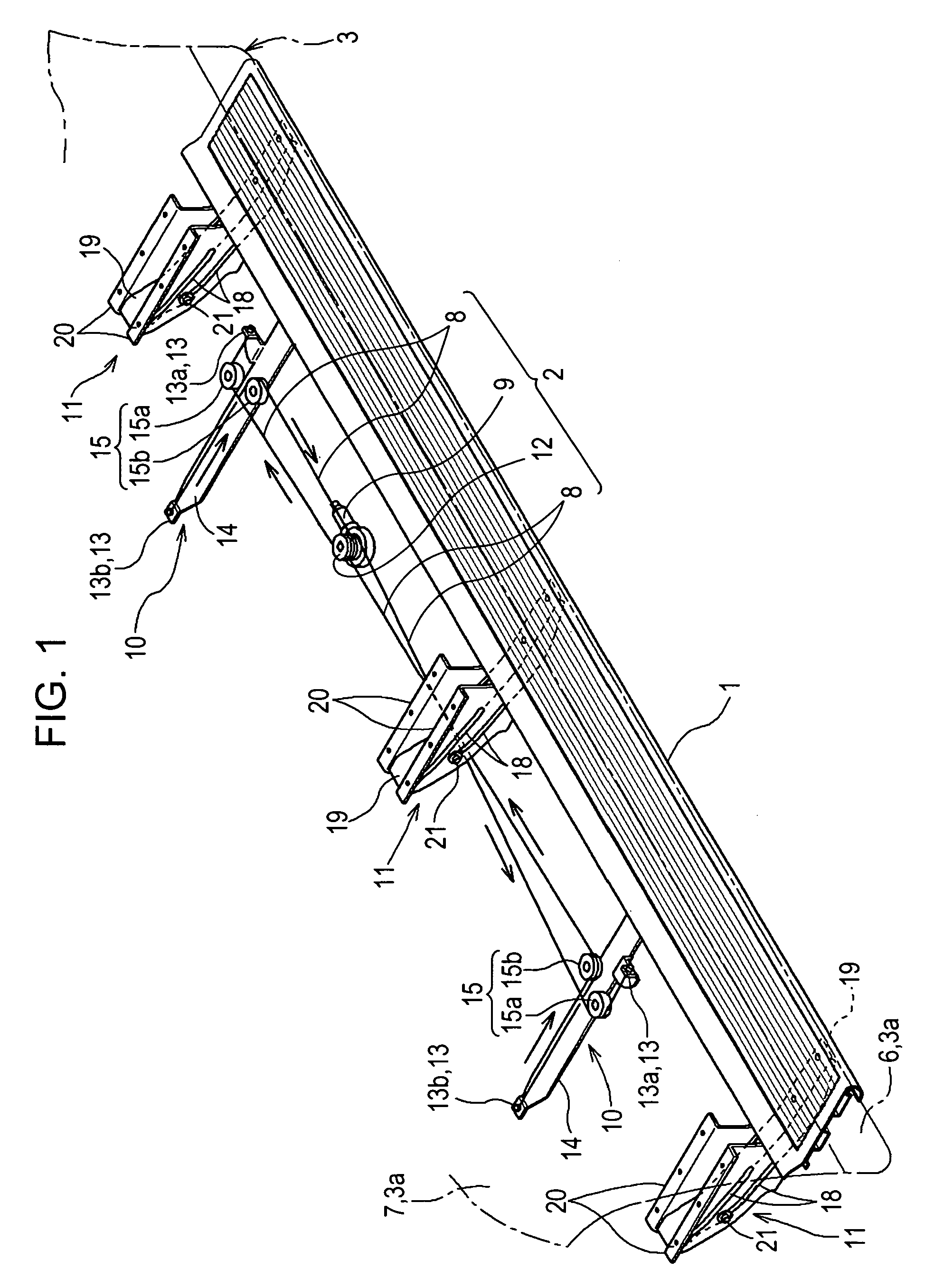
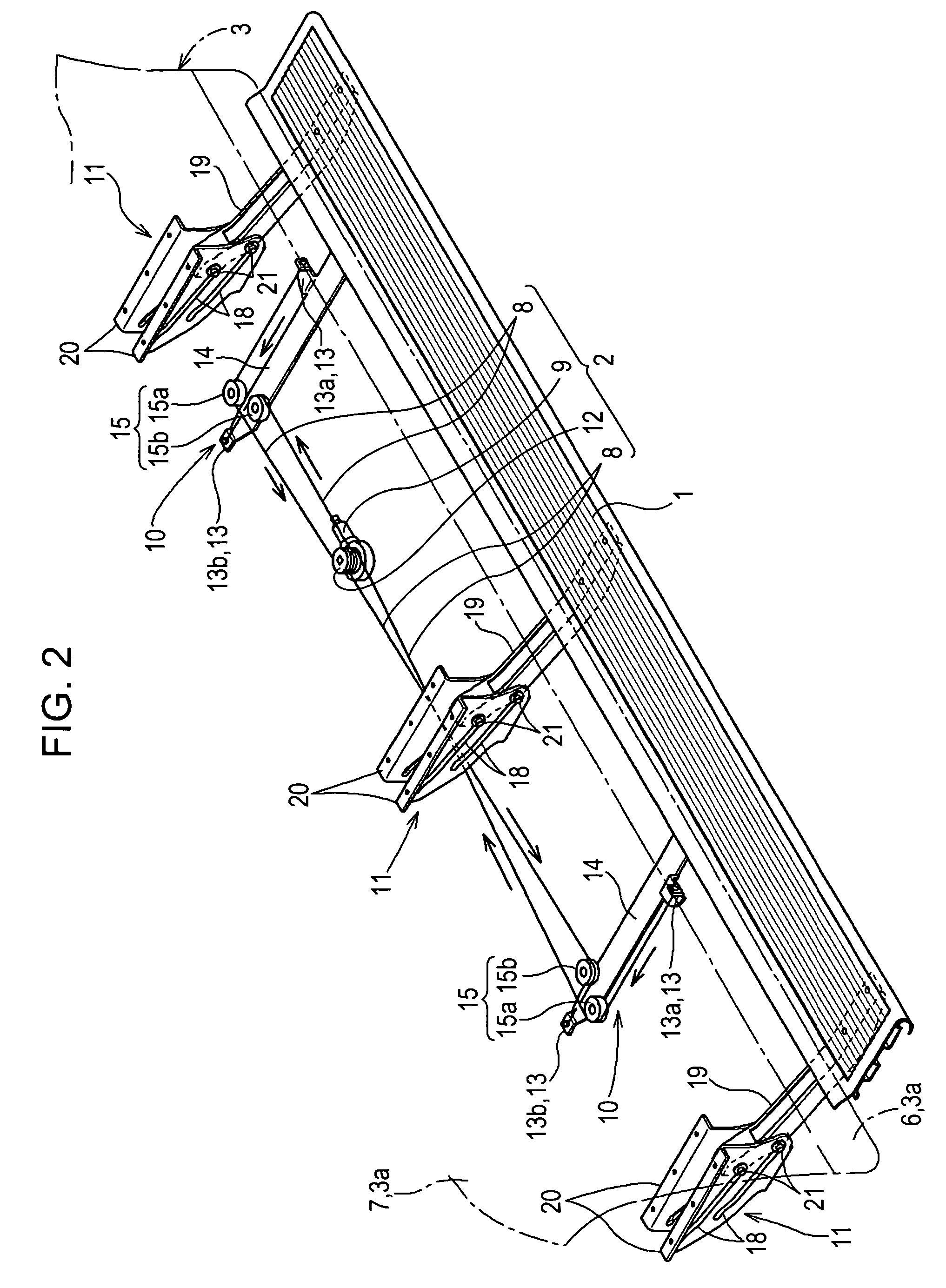
[0053]A step apparatus according to an embodiment of the present invention will be described below with reference to the accompanying drawings.

[0054]Referring to FIGS. 1 and 2, the step apparatus includes a step body 1 that can move between a projecting position and a retracted position and a drive unit 2 that drives the step body 1.

[0055]FIG. 1 is a perspective view of the step apparatus in the state in which the step body 1 is at the retracted position and FIG. 2 is a perspective view of the step apparatus in the state in which the step body 1 is at the projecting position.

[0056]The step body 1 extends along the front-rear direction of a vehicle 3. As shown in FIG. 3, which is a vertical sectional view taken along a plane perpendicular to the front-rear direction of the vehicle 3, the retracted position is a position where the step body 1 is retracted behind a side surface 3a of the vehicle 3. In addition, as shown in FIG. 4, which is also a vertical sectional view taken along a p...


PUM


Abstract

A step apparatus includes a step body that can move between a projecting position where the step body projects from a side surface of the vehicle and a retracted position where the step body is retracted behind the side surface of the vehicle, a drive unit for driving the step body, the drive unit including a rope-shaped member connected to the step body, a rotating drum around which the rope-shaped member is wound, and a drive motor that rotates the rotating drum, and a guide unit for guiding the movement of the step body between the projecting position and the retracted position.

Description

CROSS REFERENCES TO RELATED APPLICATIONS[0001]This application is based on and claims priority under 35 U.S.C. §119 with respect to Japanese Patent Application No. 2005-019298 filed on Jan. 27, 2005, the entire contents of which is incorporated herein by reference.BACKGROUND OF THE INVENTION[0002]1. Field of the Invention[0003]The present invention relates to a step apparatus including a step body that can move between a projecting position where the step body projects from a side surface of a vehicle and a retracted position where the step body is retracted behind the side surface of the vehicle and a drive unit that drives the step body.[0004]2. Description of the Related Art[0005]In such a step apparatus, when an occupant tries to get into or out of the vehicle, the drive unit drives the step body to the projecting position so that the step body projects outward and assists the occupant in getting into or out of the vehicle.[0006]When the vehicle drives, the drive unit drives the...

Claims


Application Information

Patent Timeline
Patent Type & Authority Patents(United States)
IPC IPC(8): B60R3/02
CPCB60R3/02
Inventor KOBAYASHI, NORIKAZU
Owner AISIN SEIKI KK
Why Eureka
Try Eureka