
Spectacle lens and spectacles

a technology of spectacles and lenses, applied in the field of corrective lenses, can solve the problems of large aberrations, large aberrations, and conventional wrap-around spectacles configured as non-corrective lenses, and achieve the effect of excellent optical performan

Active Publication Date: 2008-11-04
HOYA LENS THAILAND LTD +1
View PDF16 Cites 11 Cited by
  • Summary
  • Abstract
  • Description
  • Claims
  • Application Information

AI Technical Summary

Benefits of technology

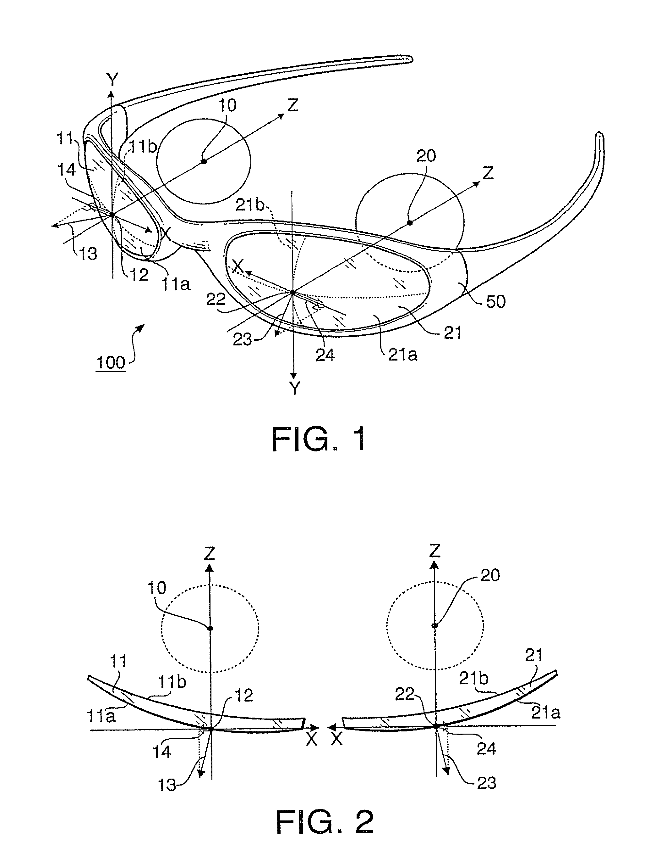
The present invention provides a spectacle lens that can be fitted into a frame with a large front warframe angle, such as wrap-around spectacles. The lens has an aspherical surface on both its front and back surfaces, which allows for the correction of asymmetrical aberrations caused when the lens is designed to cover a temporal region side of the eye. The lens also has a suitable wrapping property of covering a temporal region side of the eye, even when fitted into a frame with a large front warframe angle. The lens has an angle formed between the outward normal line and the axis passing through the centration point and the center of rotation of the eye that is larger than 10 degrees, which allows for excellent optical performance even when fitted into a frame with a large front warframe angle. The aspheric amount of the lens is determined based on the condition that the angle formed between the outward normal line and the axis passing through the centration point and the center of rotation of the eye is larger than 10 degrees. The lens can be designed as a plus or minus lens to reduce asymmetrical aberrations. Overall, the present invention provides a spectacle lens that can achieve excellent optical performance even when fitted into a frame with a large front warframe angle.

Problems solved by technology

However, most of the conventional wrap-around spectacles are configured as a non-corrective lens (i.e., glasses having no dioptric power).
However, when such a spherical lens is worn by a wearer, even a visual axis defined when the wearer faces the front can not avoid intersecting with a lens surface obliquely.
Therefore, large aberrations are caused when the spherical lens is used to correct visual acuity.
Providing a negative power to a spherical lens having a deep base curve can lead to large aberrations even if the spectacle frame to which the spherical lens is to be fitted has no front warpage angle.
For this reason, the degree of freedom of lens design is limited, and thereby optical performance such as an aberration correction function is deteriorated.
Since the spectacle lens disclosed in JP HEI 5-323185A is designed such that an inclination angle at a centration point is relatively small and a base curve is relatively shallow, the degree of wraparound becomes small and thereby the degree of covering the temporal region side of a head (i.e., a wrapping property) becomes insufficient.
However, since both of back and front surfaces of the spectacle lens disclosed in JP 2000-506628A are designed to be symmetric, it is impossible in principle to correct asymmetrical aberrations which increase as the inclination angle at the centration point becomes larger.

Method used


Image

  • Spectacle lens and spectacles
  • Spectacle lens and spectacles
  • Spectacle lens and spectacles

Examples


first example

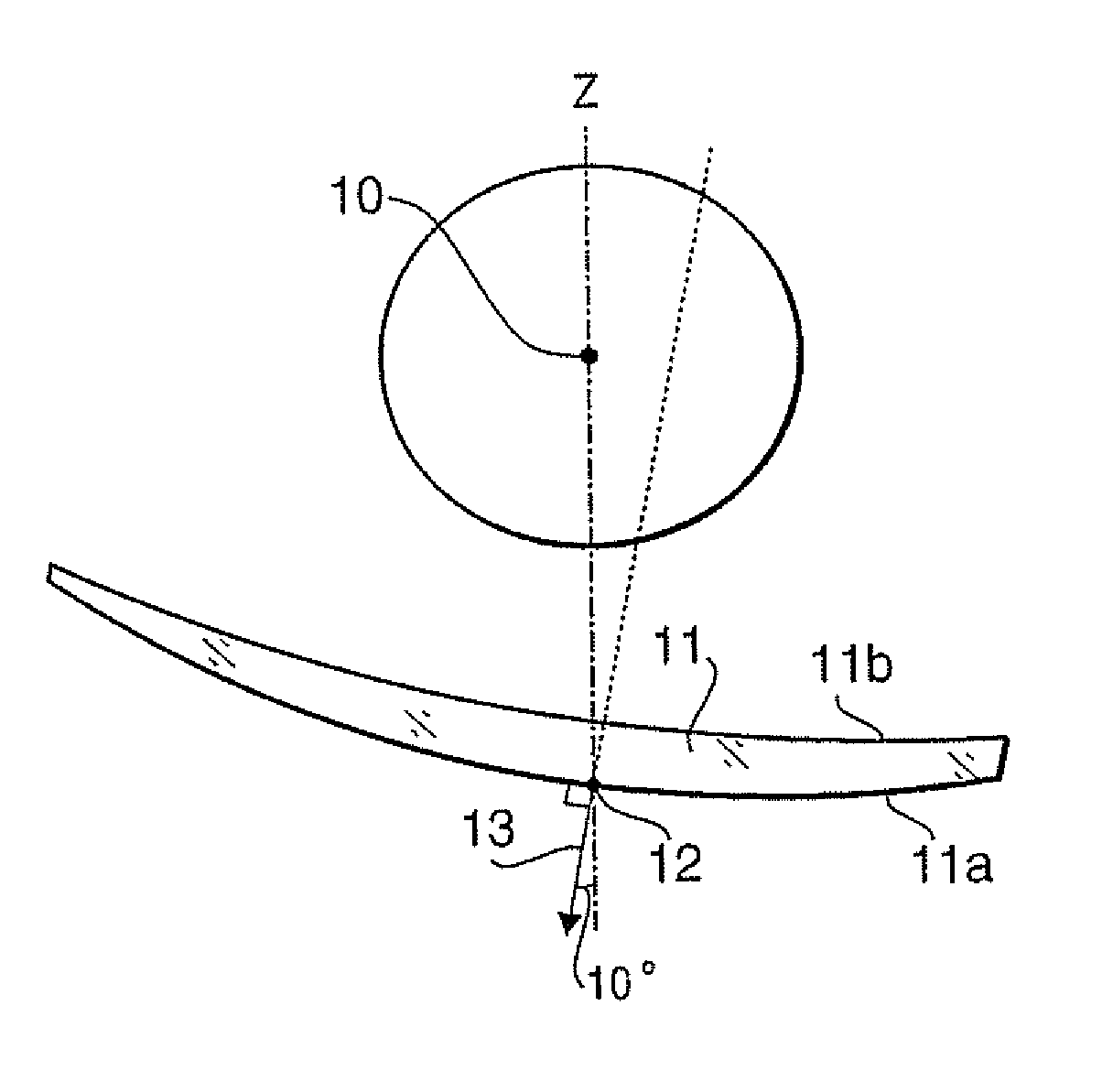
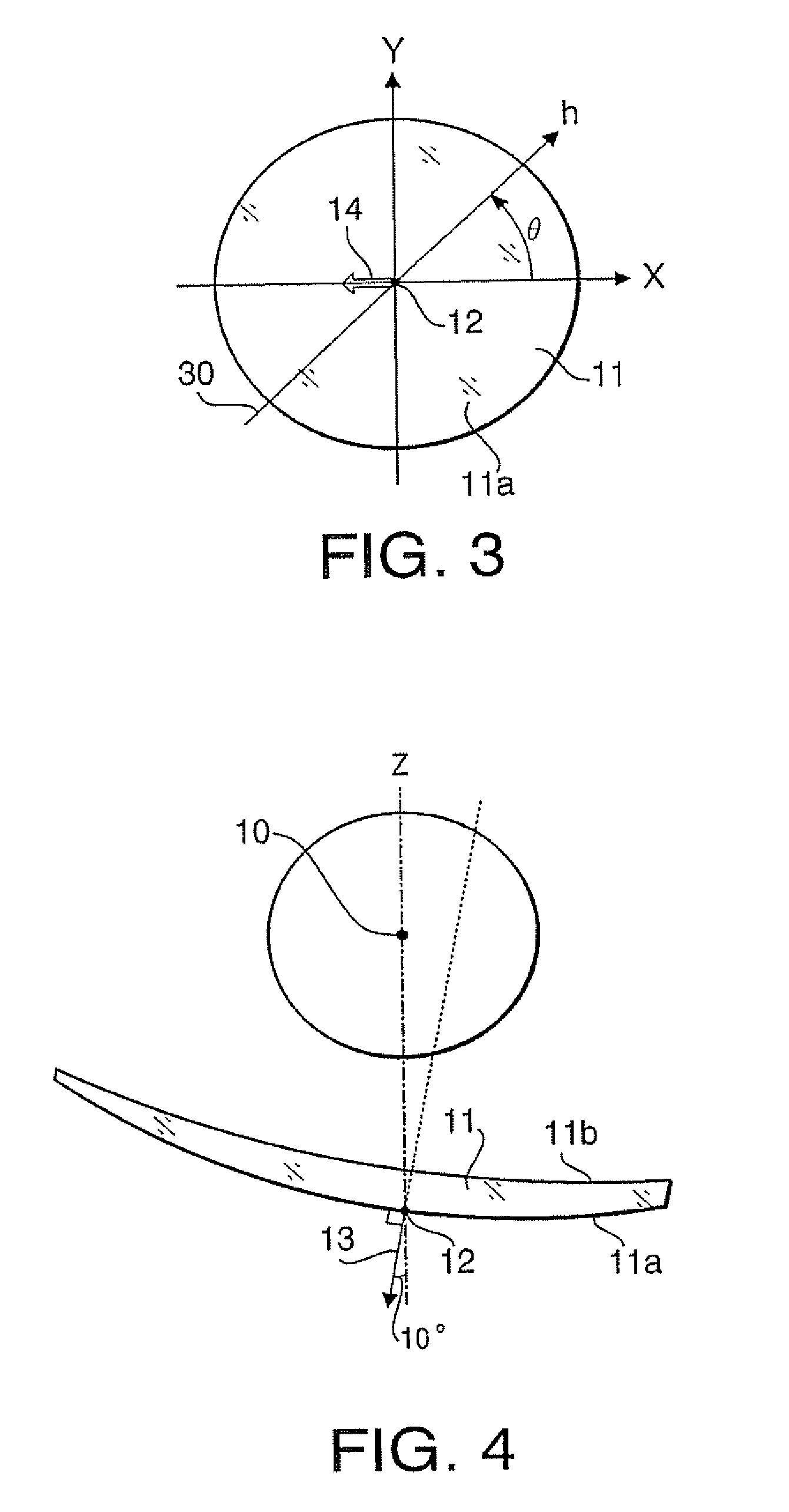
[0129]FIG. 4 is a cross-section of the spectacle lens 11 according to a first example defined in the X-Z plane. The spectacle lens 11 according to the first example is configured such that the angle formed between the outward normal line 13 and the Z-axis (i.e., a front warpage angle) is 10°. FIG. 5 is a graph of the cross-section surface power D1 of the front surface 11a with respect to the distance h and the angle θ. As shown in FIG. 5, the front surface 11a of the spectacle lens 11 is formed as a spherical surface. FIG. 6 is a graph of the cross-section surface power D2 of the back surface 11b with respect to the distance h and the angle θ. As shown in FIG. 6, the back surface 11b is formed as an aspherical surface having the cross-section surface power which varies depending on the values of the distance h and the angle θ.

[0130]FIG. 7 is a graph illustrating the aspheric amount ΔP˜ with respect to the distance h and the angle θ. The aspheric amount is obtained by using the cross...

second example

[0136]FIG. 2 is a cross-section of the spectacle lens 11 according to a second example define in the X-Z plane. The spectacle lens 11 according to the second example is configured such that the angle formed between the outward normal line 13 and the Z-axis (i.e., a front warpage angle) is 10°. FIG. 13 is a graph of the cross-section surface power D1 of the front surface 11a with respect to the distance h and the angle θ. As shown in FIG. 13, the front surface 11a of the spectacle lens 11 is formed as a spherical surface. FIG. 14 is a graph of the cross-section surface power D2 of the back surface 11b with respect to the distance h and the angle θ. As shown in FIG. 14, the back surface 11b is formed as an aspherical surface having the cross-section surface power which varies depending on the values of the distance h and the angle θ.

[0137]FIG. 15 is a graph illustrating the aspheric amount ΔP˜ with respect to the distance h and the angle θ. The aspheric amount is obtained by using the...

third example

[0145]FIG. 20 is a cross-section of the spectacle lens 11 according to a third example defined in the X-Z plane. The spectacle lens 11 according to the third example is configured such that the angle formed between the outward normal line 13 and the Z-axis (i.e.; a front warpage angle) at the centration point 12 is 20°. FIG. 21 is a graph of the cross-section surface power D1 of the front surface 11a with respect to the distance h and the angle θ. As shown in FIG. 21, the front surface 11a of the spectacle lens 11 is formed as a spherical surface. FIG. 22 is a graph of the cross-section surface power D2 of the back surface 11b with respect to the distance h and the angle θ. As shown in FIG. 22, the back surface 11b is formed as an aspherical surface having the cross-section surface power which varies depending on the values of the distance h and the angle θ.

[0146]FIG. 23 is a graph illustrating the aspheric amount ΔP˜ with respect to the distance h and the angle θ. The aspheric amou...


PUM


Abstract

A spectacle lens having an aspherical surface on its one of front and back surfaces is provided. An outward normal line normal to the front surface at a centration point inclines with respect to an axis passing through the centration point and a center of rotation of an eye. A cross section of the aspherical surface defined by a plane including the outward normal line and the axis is asymmetrical.

Description

BACKGROUND OF THE INVENTION[0001]The present invention relates to a corrective lens, in particular to a spectacle lens having a large front warpage angle.[0002]So-called wrap-around spectacles configured to have a relatively large front warpage angle to protect eyes of a wearer from light, wind, particles, etc., which would enter the eyes from temporal region sides of a head, have become widespread. However, most of the conventional wrap-around spectacles are configured as a non-corrective lens (i.e., glasses having no dioptric power). There are demands to use wrap-around spectacles which can provide proper visual acuity to a person who needs correction of visual acuity.[0003]A spherical lens having a deep base curve (approximately 8 dioptre) formed to fit into a spectacle frame having a large front warpage angle such as wrap-around spectacles has been proposed. However, when such a spherical lens is worn by a wearer, even a visual axis defined when the wearer faces the front can no...

Claims


Application Information

Patent Timeline
Patent Type & Authority Patents(United States)
IPC IPC(8): G02C7/02
CPCG02C7/02
Inventor SHIRAYANAGI, MORIYASUFUJII, HIROAKI
Owner HOYA LENS THAILAND LTD
Learn More