Supercharge Your Innovation With Domain-Expert AI Agents!

Fused elbow terminator and stage-fused transformer loop system

a technology of stage-fused underground transformers and loop systems, which is applied in the direction of coupling device details, coupling contact members, coupling device connections, etc., can solve the problems of time-consuming and sometimes very complex process of locating fault cables or transformers, and the proportion of or all transformers in the loop system will be out of servi

Inactive Publication Date: 2008-11-04
WHYTE GREGORY P
View PDF6 Cites 5 Cited by
  • Summary
  • Abstract
  • Description
  • Claims
  • Application Information

AI Technical Summary

Benefits of technology

This solution significantly reduces the time and complexity of diagnosing faults, minimizing power outages and damage to transformers and cables, allowing for faster restoration of service and reducing customer and business losses.

Problems solved by technology

In operation, if a cable is fault, or a transformer has problem, a portion of or all transformers in the loop system will be out of service, and the customers will have power outage.
The process of locating a fault cable or failed transformer is a time consuming and sometimes a very complex process.
The lengthy power down time causes inconvenience to customers and financial loss to business.
However, these fault indicators have been found not sensitive and their response is very unreliable.
Furthermore, many existing loop systems do not have fault indicators installed, therefore, locating a fault cable or failed transformer frequently uses process elimination approach to gradually narrow down the possibilities.
The problem is a fault cable between transformers Tx3 and Tx4.
Therefore, the problem is a fault cable between transformers Tx3 and Tx4.
Within this time the investigator has to drive among the transformers and to the lateral switch multiple times. Within this process, the lateral switch needs to be closed multiple times, each of them causes a fault current among a section of the loop system under the diagnosis test, which could cause further fault cables or transformer failures due to the high level fault current.
It is not uncommon that more cables and transformers are damaged during the process of the existing diagnosis process.
The process further lengthens, and potential damages to the cables and transformers due to the fault current further increase.

Method used


Image

  • Fused elbow terminator and stage-fused transformer loop system
  • Fused elbow terminator and stage-fused transformer loop system
  • Fused elbow terminator and stage-fused transformer loop system

Examples


Embodiment Construction

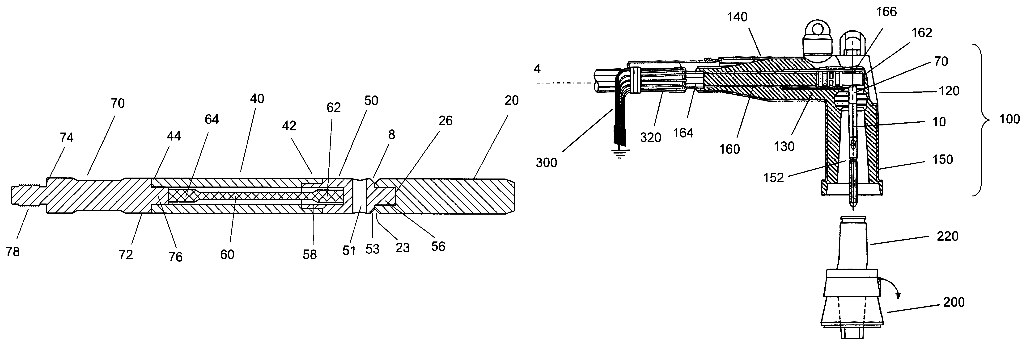
[0024]In one aspect, the present invention provides a fused pin for adapting to the existing elbow terminator used for underground transformers.

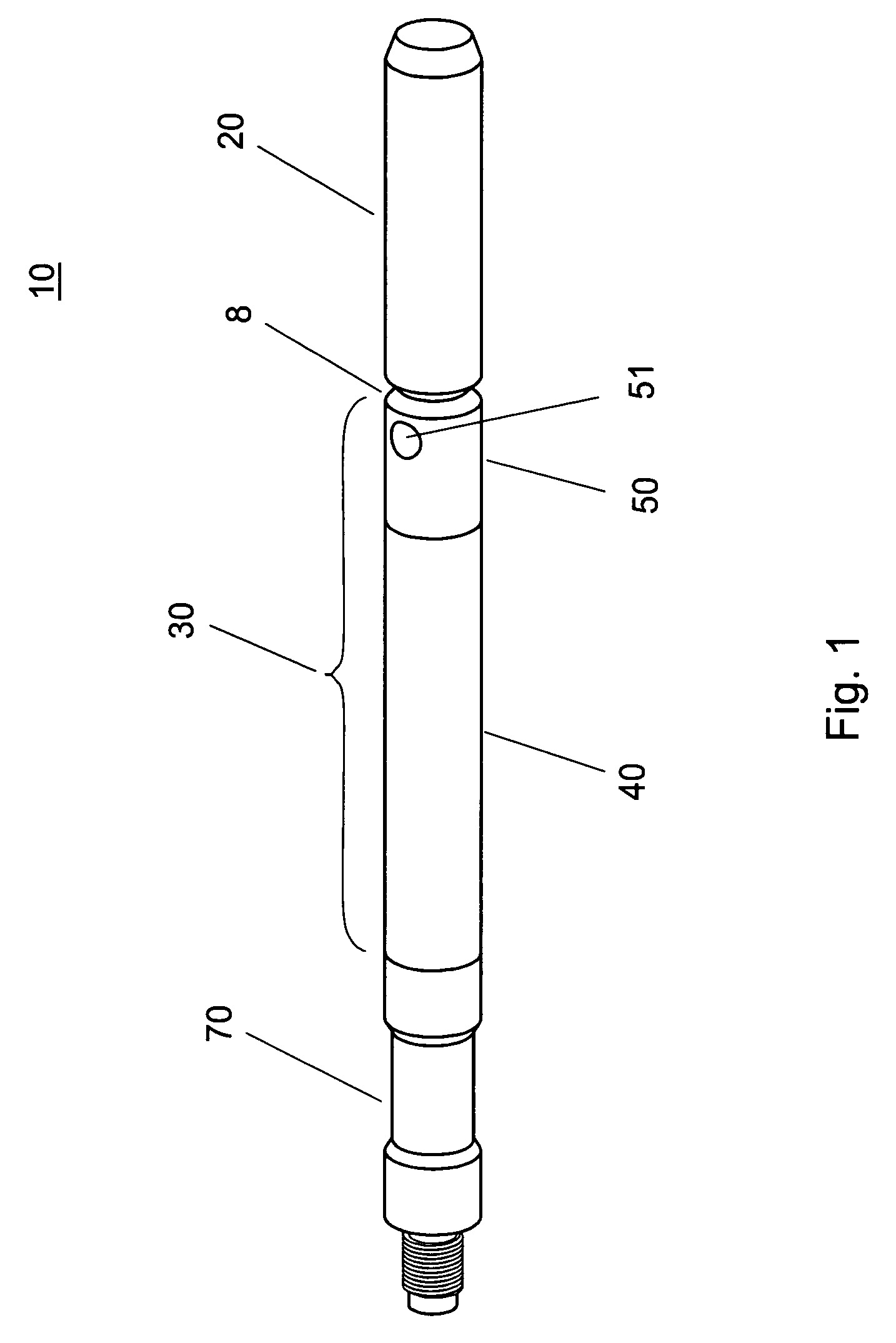
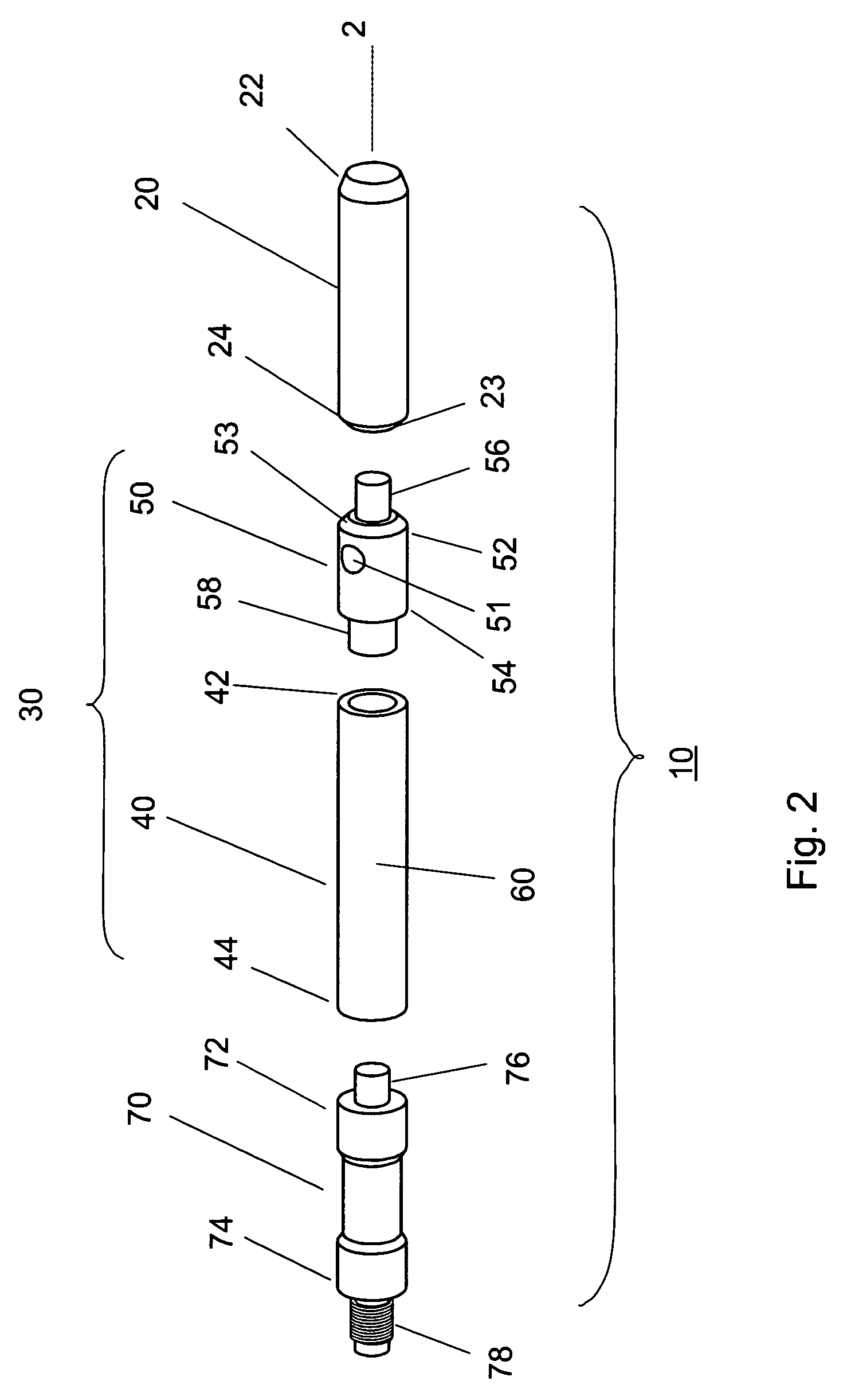
[0025]In one embodiment as shown in FIGS. 1-3, fused pin 10 has a cylindrical shape, and typically has a length about 9 inch and a diameter about 0.3 inch, which can be connected to an existing elbow terminator. Fused pin 10 includes three interconnected sections, arc follower section 20, fuse section 30 and cable interface section 70.

[0026]As illustrated in FIGS. 1 to 3, arc follower section 20 has an elongated cylindrical shape, and has a front end 22 and a rear end 24. In one embodiment, rear end 24 has a recess 26 as an interface for connection with fuse section 30. Alternatively, rear end 24 can have a protrusion (not shown) as an interface for connection with fuse section 30. Other suitable connection means, such as threaded interface, can also be used for the purpose of the present invention. Arc follower section 20 is made of an elec...


PUM


Abstract

A fused elbow terminator is disclosed which includes an elbow connector having a housing and a cable connector disposed within; and a fused pin connected to the cable connector. The fused pin includes an arc follower section, a fuse section and a cable interface section. Further disclosed is a stage-fused underground transformer loop system, which includes a series of transformers connected sequentially by a series of cables, and a series of fused elbow terminators connected to the inlets and outlets of the transformers. The fused elbow terminators are arranged in an order of decreasing the fuse capacity starting from the feed. A method of rapid diagnosis of a fault cable or a transformer failure using the stage-fused transformer loop system is also disclosed.

Description

FIELD OF THE INVENTION[0001]The present invention relates to a fused elbow terminator, a stage-fused underground transformer loop system, and a method of diagnosis of a fault cable or transformer failure by stage fusing a transformer loop system.BACKGROUND OF THE INVENTION[0002]Currently, in the United States the electrical power supply is most commonly provided using underground transformers. Typically, the transformers supplying power to an area are arranged into a loop system. One transformer loop system usually includes 8 to 50 transformers, and each transformer supplies power to 1 to 16 customers. Within the loop system, the transformers are sequentially connected one to another by a series of cables. Each cable is connected to the inlet of a transformer and the outlet of an immediate preceding transformer by two elbow terminators. The first and the last transformers are connected to a power source, such as an overhead power line. Within each loop system there is a normal open ...

Claims


Application Information

Patent Timeline
Patent Type & Authority Patents(United States)
IPC IPC(8): H01R13/64
CPCH01R13/53H01R13/68
Inventor WHYTE, GREGORY P.
Owner WHYTE GREGORY P
Features
  • R&D
  • Intellectual Property
  • Life Sciences
  • Materials
  • Tech Scout
  • Unparalleled Data Quality
  • Higher Quality Content
  • 60% Fewer Hallucinations
Learn More