
Variable magnification optical system and image taking apparatus provided therewith

a technology of optical system and magnification, applied in the field of variable magnification optical system and image taking apparatus provided therewith, can solve the problem of relativly large scale of chromatic aberration, and achieve the effect of suppressing (correcting) chromatic aberration

Active Publication Date: 2008-11-04
KONICA MINOLTA PHOTO IMAGING
View PDF13 Cites 9 Cited by
  • Summary
  • Abstract
  • Description
  • Claims
  • Application Information

AI Technical Summary

Benefits of technology

[0015]In order to solve the problem described above, the present invention has been made, and it is an object of the invention to provide a high-performance variable magnification optical system or the like, which while being compact, can suppress (correct) chromatic aberration and the like.

Problems solved by technology

Thus, in a case where the optical prism is decentered when built into an optical system (variable magnification optical system) inside the image taking apparatus (for example, when a surface of the optical prism is inclined from a desired position), there is a risk that a relatively large scale of chromatic aberration, attributable to the decentering, occurs so as to achieve a high zoom ratio.

Method used


Image

  • Variable magnification optical system and image taking apparatus provided therewith
  • Variable magnification optical system and image taking apparatus provided therewith
  • Variable magnification optical system and image taking apparatus provided therewith

Examples


first embodiment

[0093]The embodiment of the present invention will be described with reference to the accompanying drawings.

[1. Digital Camera]

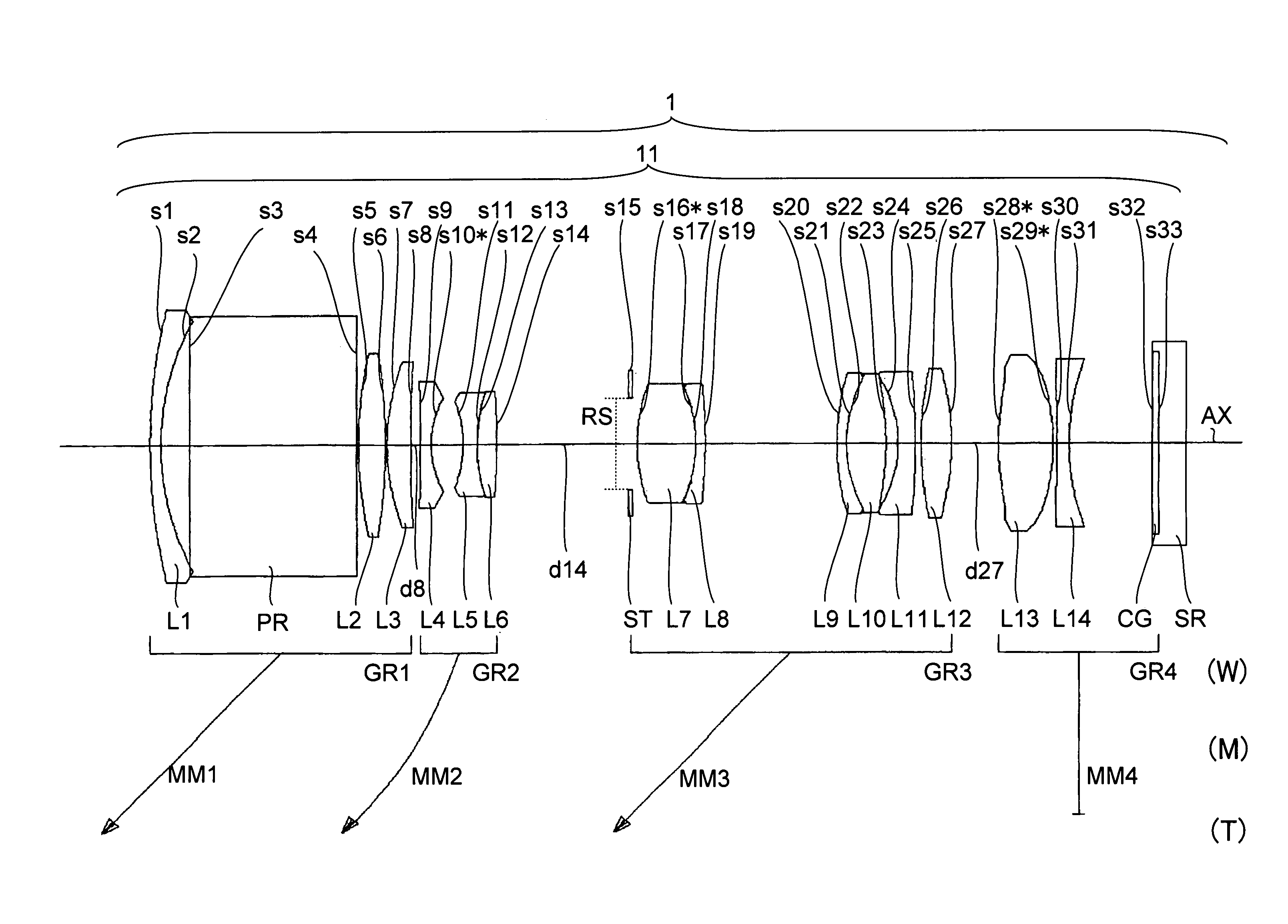
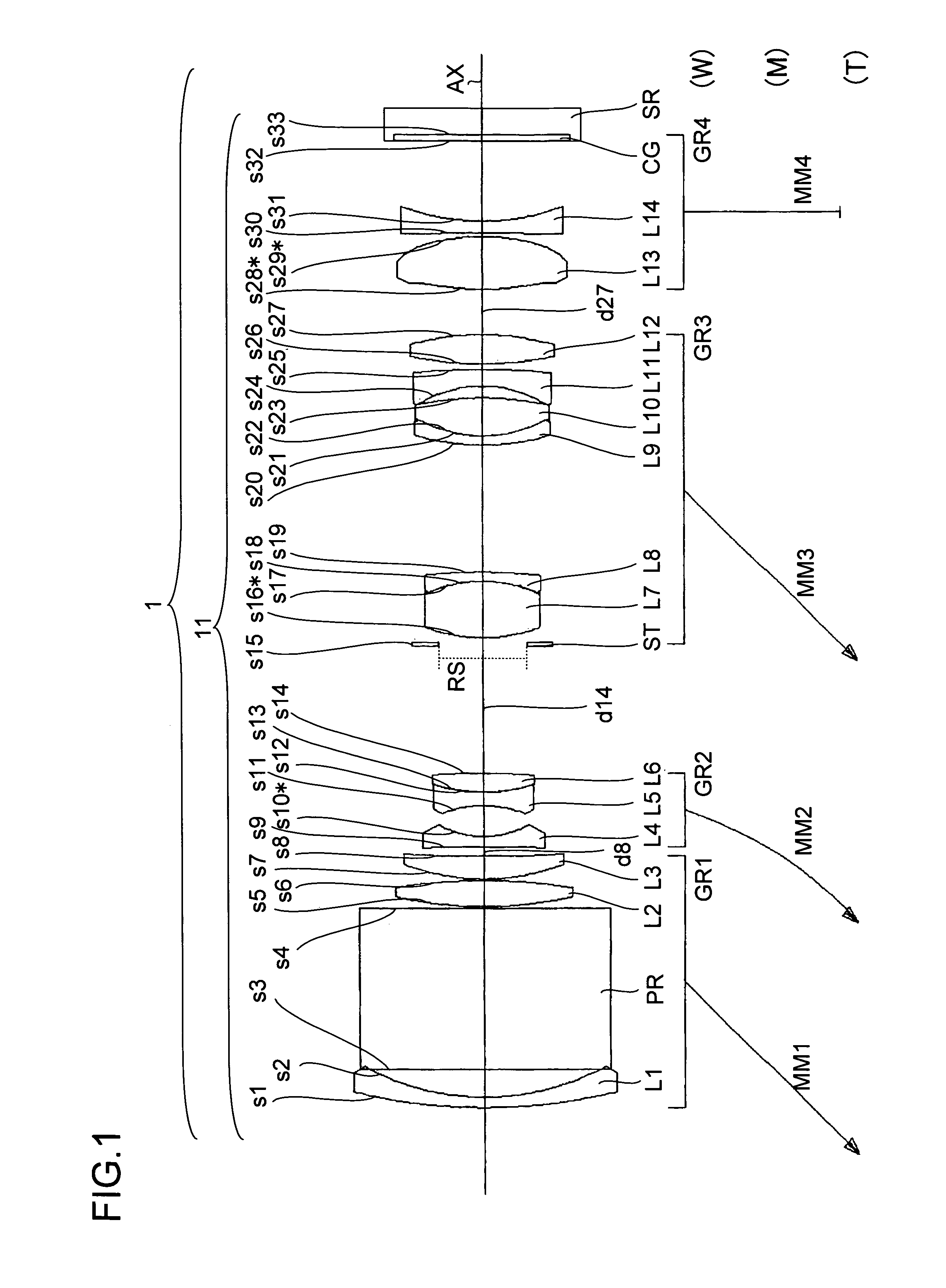
[0094]FIGS. 5 and 6 are schematic block diagrams of a digital camera 29 as one example of an image taking apparatus of the invention. FIG. 5 shows the internal block construction of each part and an optical unit 1 (configured to include a variable magnification optical system 11 and an image sensor SR) built in the digital camera 29. FIG. 6 shows the side of the digital camera 29, indicating, in particular, one example of the variable magnification optical system 11 included in the optical unit 1. A U direction, a V direction, and a Z direction in the digital camera 29 denote the height, the width, and the depth, respectively.

[0095]As shown in FIG. 5, the digital camera 29 includes the variable magnification optical system 11, an optical system driving part 13, the image sensor SR, a signal processing part 14, a display part 15, a recording part 16, a record...


PUM


Abstract

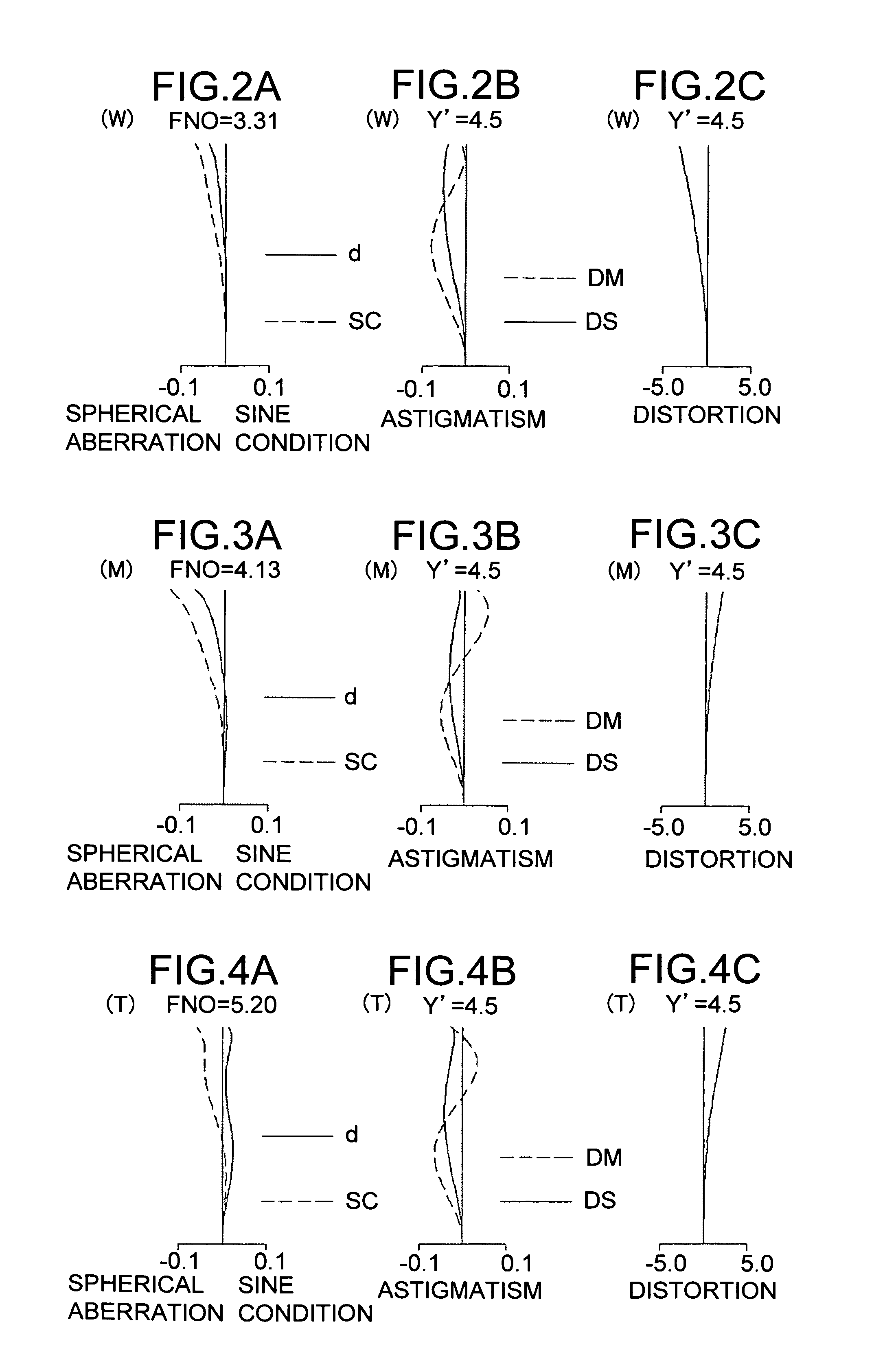
A variable magnification optical system includes lens units that focus a ray of light from an object side on an image sensor, in which the lens unit located at a first position from the object side toward the image side includes an optical path changing element for changing an optical path. The variable magnification optical system performs magnification variation by changing gaps between the lens units, and satisfies predetermined conditional formulae.

Description

[0001]This application is based on JP-A-2005-224257 filed on Aug. 2, 2005, the contents of which are hereby incorporated by reference.BACKGROUND OF THE INVENTION[0002]1. Field of the Invention[0003]The present invention relates to a variable magnification optical system for use in an optical unit or the like, and to an image taking apparatus provided with this variable magnification optical system.[0004]2. Description of the Prior Art[0005]In recent years, following the widespread use of personal computers (PCs), digital cameras (image taking apparatuses) capable of easily taking in an image have been widespread. Thus, as is the case with cameras using a silver halide film (silver halide film cameras), there has been a demand imposed on such digital cameras for downsizing (slimming-down) and performance enhancement (for example, high magnification variation function and high aberration correction function).[0006]For example, image taking apparatuses disclosed in patent publications ...

Claims


Application Information

Patent Timeline
Patent Type & Authority Patents(United States)
IPC IPC(8): G02B15/14
CPCG02B15/173G02B15/144113
Inventor YAMAMOTO, YASUSHIMATSUMOTO, HIROYUKIMASUI, ATSUO
Owner KONICA MINOLTA PHOTO IMAGING
Learn More