Optical system, image capturing module, electronic device and carrier

A technology for optical systems and electronic equipment, applied in the fields of electronic equipment and vehicles, optical systems, and imaging modules, can solve problems such as affecting the driver's driving judgment, low resolution, and unsatisfactory image clarity and sharpness. Achieve good optical performance, share the burden of bending force, and achieve the effect of viewing angle characteristics

Active Publication Date: 2021-08-10
JIANGXI JINGCHAO OPTICAL CO LTD
View PDF6 Cites 3 Cited by
  • Summary
  • Abstract
  • Description
  • Claims
  • Application Information

AI Technical Summary

Problems solved by technology

[0003] In related technologies, the resolution of the mainstream monitoring camera equipment on the market is relatively low, and the overall clarity and sharpness of the images taken when driving at night are not ideal, so that it affects the driver's driving judgment

Method used


Image

  • Optical system, image capturing module, electronic device and carrier
  • Optical system, image capturing module, electronic device and carrier
  • Optical system, image capturing module, electronic device and carrier

Examples


Embodiment 1

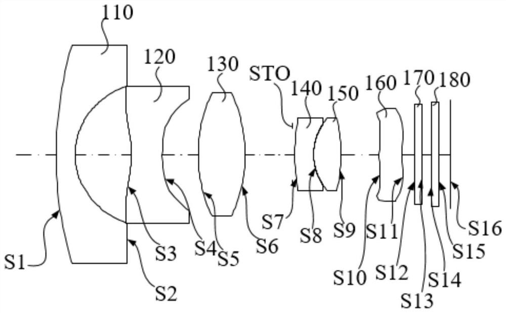
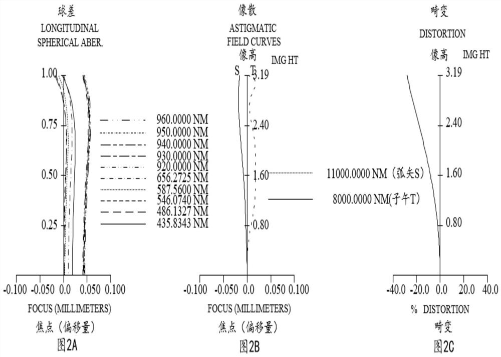
[0083] Please refer to Figure 1 to Figure 2C As shown, the optical system 100 includes a first lens 110, a second lens 120, a third lens 130, a diaphragm STO, a fourth lens 140, a fifth lens 150, and a sixth lens arranged sequentially along the optical axis from the object side to the image side. The lens 160, the infrared filter 170, the protective glass 180 and the imaging surface S16.

[0084] The first lens 110 has a negative refractive power, the object side S1 of the first lens 110 is convex at the near optical axis, and the image side S2 of the first lens 110 is concave at the near optical axis.

[0085] The second lens 120 has a negative refractive power. The object side S3 of the second lens 120 is concave at the near optical axis, and the image side S4 of the second lens 120 is also concave at the near optical axis.

[0086] The third lens 130 has a positive refractive power. The object side S5 of the third lens 130 is convex at the near optical axis, and the image...

Embodiment 2

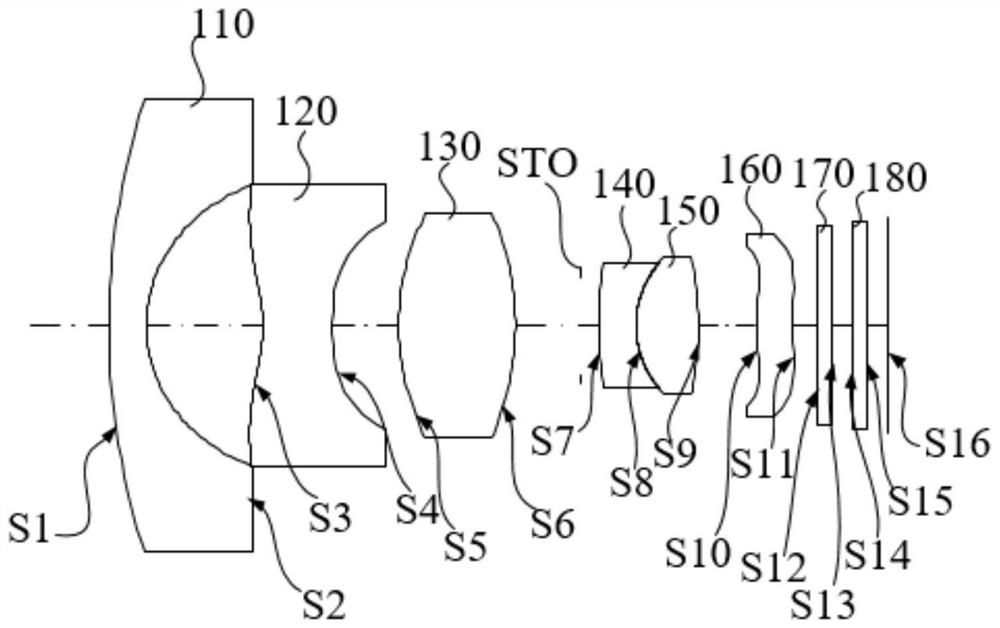
[0107] Please refer to Figure 3 to Figure 4C As shown, the optical system 100 includes a first lens 110, a second lens 120, a third lens 130, a diaphragm STO, a fourth lens 140, a fifth lens 150, and a sixth lens arranged sequentially along the optical axis from the object side to the image side. The lens 160, the infrared filter 170, the protective glass 180 and the imaging surface S16.

[0108] The first lens 110 has a negative refractive power, the object side S1 of the first lens 110 is convex at the near optical axis, and the image side S2 of the first lens 110 is concave at the near optical axis.

[0109] The second lens 120 has a negative refractive power, and both the object side S3 of the second lens 120 and the image side S4 of the second lens 120 are concave at the near optical axis.

[0110] The third lens 130 has a positive refractive power, and both the object side S5 of the third lens 130 and the image side S6 of the third lens 130 are convex at the near optic...

Embodiment 3

[0128] Please refer to Figure 5 to Figure 6C As shown, the optical system 100 includes a first lens 110, a second lens 120, a third lens 130, a diaphragm STO, a fourth lens 140, a fifth lens 150, and a sixth lens arranged sequentially along the optical axis from the object side to the image side. The lens 160, the infrared filter 170, the protective glass 180 and the imaging surface S16.

[0129] The first lens 110 has a negative refractive power, the object side S1 of the first lens 110 is convex at the near optical axis, and the image side S2 of the first lens is concave at the near optical axis.

[0130] The second lens 120 has a negative refractive power, and both the object side S3 of the second lens 120 and the image side S4 of the second lens 120 are concave at the near optical axis.

[0131] The third lens 130 has a positive refractive power, and both the object side S5 of the third lens 130 and the image side S6 of the third lens 130 are convex at the near optical a...


PUM


Abstract

The present invention discloses an optical system, an image capturing module, electronic device and a carrier. The optical system includes a first lens having a negative meandering force, a second lens having a negative meandering force, an image-side surface of the second lens being concave in a paraxial region thereof, a third lens having a positive meandering force, an object-side surface of the third lens being convex in a paraxial region thereof, the image side surface of the third lens is a convex surface near the optical axis; the object side surface of the fourth lens is a convex surface near the optical axis; the image side surface of the fifth lens is a convex surface near the optical axis; the object side surface of the sixth lens is a convex surface near the optical axis; and the maximum field angle FOV of the optical system, the effective focal length f of the optical system and the half Imgh of the image height corresponding to the maximum field angle of the optical system meet the condition that (FOV*f) / (2*Imgh) is larger than 40.0 deg and smaller than 53.0 deg. This design provides a high pixel optical imaging system.

Description

technical field [0001] The present application relates to the technical field of optical imaging, in particular to an optical system, an imaging module, electronic equipment and a carrier. Background technique [0002] With the development of society, the requirements for safety and monitoring in various fields are getting higher and higher, especially in the field of transportation and vehicle monitoring. [0003] In the related art, the resolution of the mainstream monitoring camera equipment on the market is relatively low, and the overall definition and sharpness of the images captured when driving at night are not ideal, so that the driving judgment of the driver is affected. Therefore, how to provide a high-pixel optical imaging system has become an urgent problem to be solved. Contents of the invention [0004] Embodiments of the present application provide an optical system, an imaging module, electronic equipment, and a carrier, and provide an optical imaging sys...

Claims


Application Information

Patent Timeline
Patent Type & Authority Applications(China)
IPC IPC(8): G02B13/00G02B13/06G02B13/18G03B30/00
CPCG02B13/0045G02B13/006G02B13/18G02B13/06
Inventor 乐宇明蔡雄宇兰宾利赵迪
Owner JIANGXI JINGCHAO OPTICAL CO LTD
Why Eureka
Try Eureka