Power output apparatus, vehicle equipped with power output apparatus, and control method of power output apparatus

a technology of power output apparatus and control method, which is applied in the direction of electric devices, machines/engines, and jet propulsion mounting, etc., can solve the problems of not achieving the effect of efficiency and performance improvemen

Inactive Publication Date: 2008-11-11
TOYOTA JIDOSHA KK
View PDF15 Cites 41 Cited by
  • Summary
  • Abstract
  • Description
  • Claims
  • Application Information

AI Technical Summary

Benefits of technology

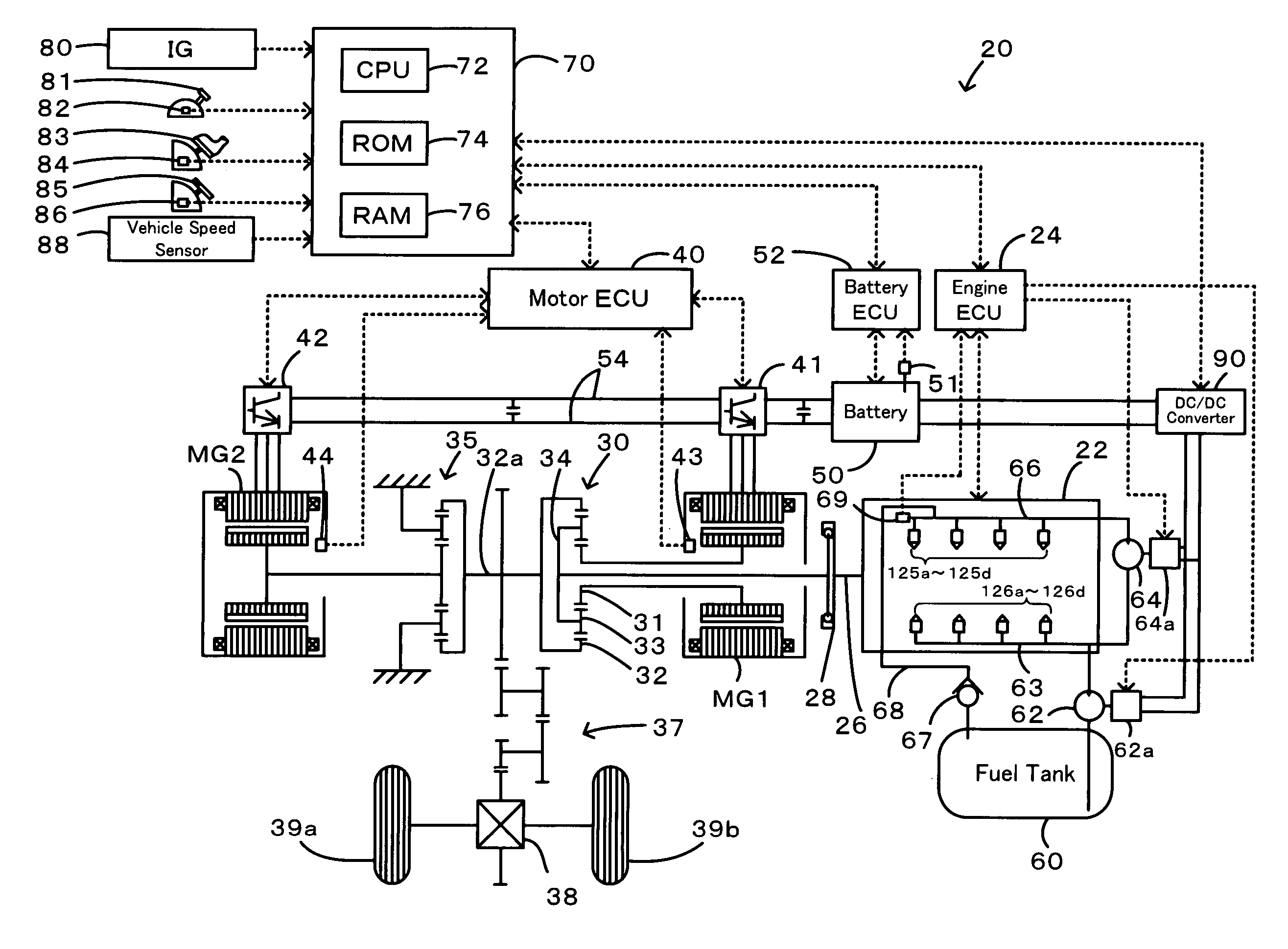
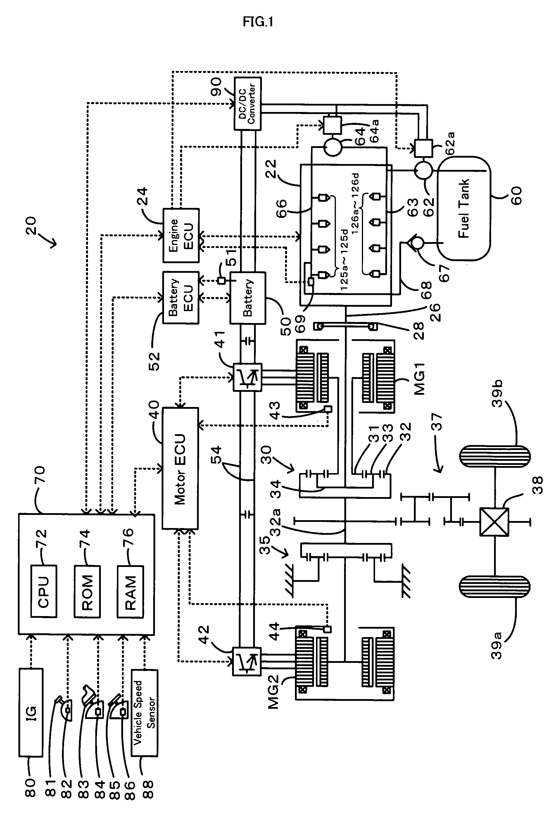
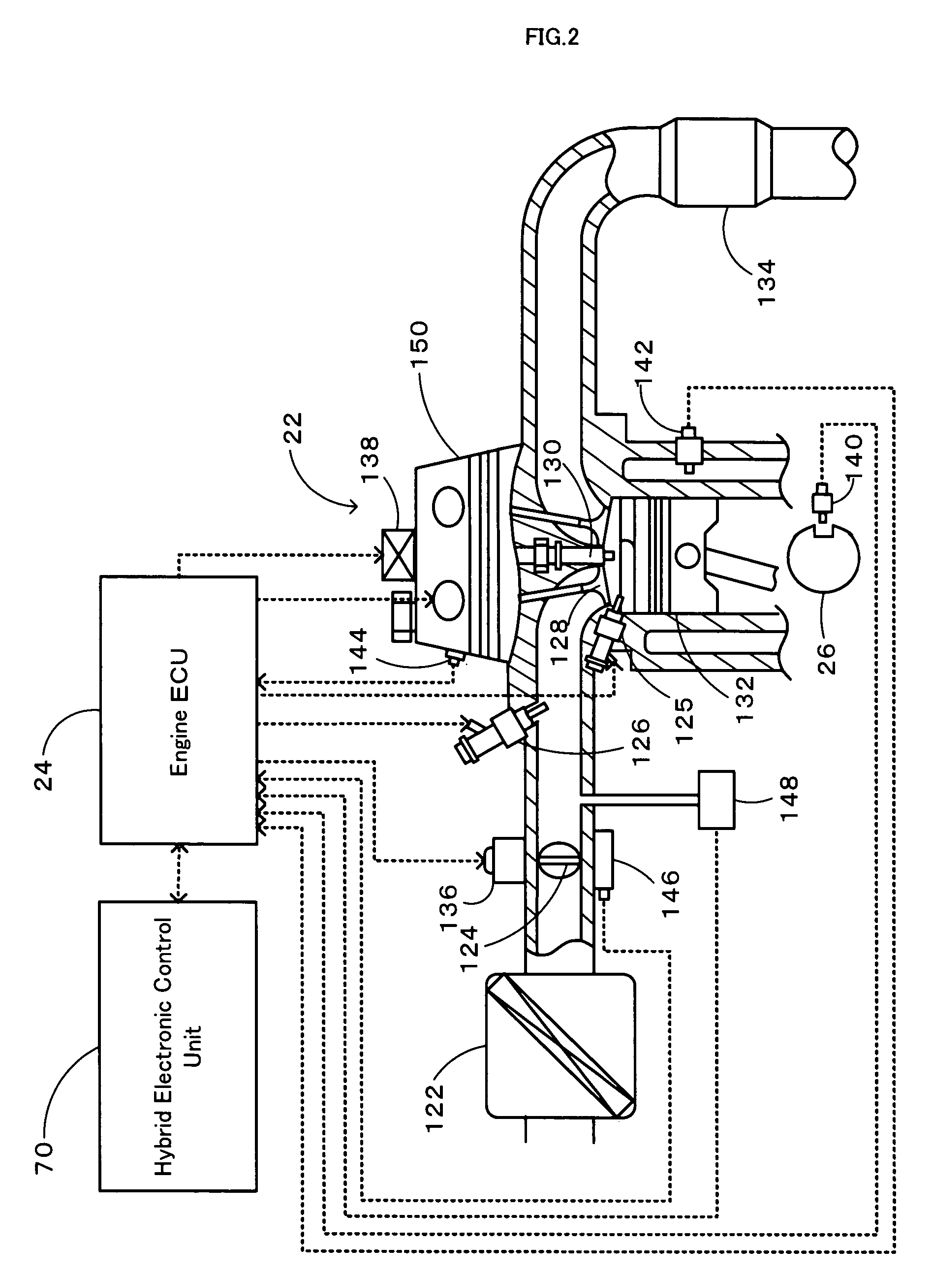
[0010]The power output apparatus of the invention sets the target power to be output from the internal combustion engine, based on the target driving force to be output to the driveshaft. The power output apparatus subsequently sets the target operating state of the internal combustion engine, based on the set target power, the specified allocation rate of fuel injection from the in-cylinder fuel injection valve to fuel injection from the port fuel injection valve, the first constraint, and the second constraint. Here the first constraint is imposed on the operating state of the internal combustion engine with shared fuel injection from the in-cylinder fuel injection valve and from the port fuel injection valve at the predetermined first allocation rate. The second constraint is imposed on the operating state of the internal combustion engine with shared fuel injection from the in-cylinder fuel injection valve and from the port fuel injection valve at the predetermined second allocation rate different from the first allocation rate. The power output apparatus then controls the internal combustion engine and the torque conversion unit to drive the internal combustion engine in the target operating state with fuel injection at the specified allocation rate and to ensure output of the target driving force to the driveshaft. Namely the target operating state of the internal combustion engine is set according to the target power to be output from the internal combustion engine, the specified allocation rate of fuel injection from the in-cylinder fuel injection valve to fuel injection from the port fuel injection valve, the first constraint imposed on the operating state of the internal combustion engine at the predetermined first allocation rate, and the second constraint imposed on the operating state of the internal combustion engine at the predetermined second allocation rate. The control of the internal combustion engine and the torque conversion unit enables operation of the internal combustion engine in the target operating state and ensures output of the target driving force to the driveshaft. The internal combustion engine is driven in the target operating state, which is set according to the specified allocation rate of fuel injection from the in-cylinder fuel injection valve to fuel injection from the port fuel injection valve. This arrangement attains efficient and appropriate operation of the internal combustion engine with shared fuel injection from the in-cylinder fuel injection valve and from the port fuel injection valve at the specified allocation rate.
[0012]In another preferable embodiment of the power output apparatus of the invention, each of the first constraint and the second constraint includes multiple restrictions with regard to multiple conditions. The target operating state setting module sets the target operating state of the internal combustion engine, based on a certain restriction included in the first constraint and a corresponding restriction included in the second constraint with regard to a selected condition among the multiple conditions. When the internal combustion engine is driven with the multiple restrictions, the arrangement of this embodiment ensures appropriate operation of the internal combustion engine with the restrictions under the selected condition. The multiple restrictions may include at least one of an efficient operation restriction for efficient operation of the internal combustion engine and a high torque output restriction for output of a high torque from the internal combustion engine.
[0019]In another preferable embodiment of the vehicle of the invention, each of the first constraint and the second constraint includes multiple restrictions with regard to multiple conditions. The target operating state setting module sets the target operating state of the internal combustion engine, based on a certain restriction included in the first constraint and a corresponding restriction included in the second constraint with regard to a selected condition among the multiple conditions. When the internal combustion engine is driven with the multiple restrictions, the arrangement of this embodiment ensures appropriate operation of the internal combustion engine with the restrictions under the selected condition.
[0026]In another preferable embodiment of the control method of the power output apparatus of the invention, each of the first constraint and the second constraint includes multiple restrictions with regard to multiple conditions. The step (b) sets the target operating state of the internal combustion engine, based on a certain restriction included in the first constraint and a corresponding restriction included in the second constraint with regard to a selected condition among the multiple conditions. When the internal combustion engine is driven with the multiple restrictions, the arrangement of this embodiment ensures appropriate operation of the internal combustion engine with the restrictions under the selected condition.

Problems solved by technology

A simple variation in allocation rate of fuel injection, however, does not attain the sufficient effects on efficiency and performance improvement.

Method used


Image

  • Power output apparatus, vehicle equipped with power output apparatus, and control method of power output apparatus
  • Power output apparatus, vehicle equipped with power output apparatus, and control method of power output apparatus
  • Power output apparatus, vehicle equipped with power output apparatus, and control method of power output apparatus

Examples


first embodiment

[0065]In the drive control routine of FIG. 11, the CPU 372 of the electronic control unit 370 first inputs various data required for control, that is, the accelerator opening Acc from the accelerator pedal position sensor 84, the vehicle speed V from the vehicle speed sensor 88, the rotation speed Nin of the input shaft 351, the rotation speed Nout of the output shaft 352, the allocation rate k of fuel injection from the in-cylinder fuel injection valves 125 to fuel injection from the port fuel injection valves 126, and the high torque request with preference to a high torque over fuel consumption (step S300). The rotation speed Nin of the input shaft 351 and the rotation speed Nout of the output shaft 352 are measured respectively by the rotation speed sensors 361 and 362 and are received from the CVTECU 359 by communication. The allocation rate k and the high torque request have been defined in the

second embodiment

[0066]After the data input, the CPU 372 sets a torque demand Tout* to be output to the output shaft 352 or the driveshaft linked with the drive wheels 39a and 39b and a vehicle power demand Pe* required for the whole motor vehicle 320, based on the input accelerator opening Acc and the input vehicle speed V (step S310). A concrete procedure of setting the torque demand Tout* in this embodiment stores in advance variations in torque demand Tout* against the accelerator opening Acc and the vehicle speed V as a torque demand setting map in the ROM 374 and reads the torque demand Tout* corresponding to the given accelerator opening Acc and the given vehicle speed V from this torque demand setting map. The torque demand setting map used in the second embodiment is similar to the map shown in FIG. 4. The vehicle power demand Pe* is obtained as the product of the torque demand Tout* and the rotation speed Nout of the output shaft 352.

[0067]The CPU 372 subsequently executes the processing o...


PUM


Abstract

The drive control of the invention sets a rotation speed Ni for in-cylinder injection according to an operation curve used in operation of an engine with fuel injection from only in-cylinder fuel injection valves and a rotation speed Np for port injection according to an operation curve used in operation of the engine with fuel injection from only port fuel injection valves (steps S150 and S160). The drive control subsequently sets a target rotation speed Ne* and a target torque Te* of the engine by distributing the rotation speed Ni for in-cylinder injection and the rotation speed Np for port injection by an allocation rate k of in-cylinder fuel injection to port fuel injection (step S170). The drive control then sets torque commands Tm1* and Tm2* of two motors and controls the engine and the two motors to drive the engine at a specific drive point defined by the target rotation speed Ne* and the target torque Te* and to ensure output of a torque demand Tr* to a ring gear shaft or a driveshaft (steps S180 through S220). This arrangement attains efficient and appropriate operation of the engine.

Description

BACKGROUND OF THE INVENTION[0001]1. Field of the Invention[0002]The present invention relates to a power output apparatus, a vehicle equipped with the power output apparatus, and a control method of the power output apparatus.[0003]2. Description of the Prior Art[0004]One proposed power output apparatus to be mounted on a vehicle has an engine with in-cylinder fuel injection valves for injecting the fuel into cylinders and a toroidal continuously variable transmission (see, for example, Japanese Patent Laid-Open Gazette No. 2000-52817). This power output apparatus sets a target torque of the engine and a target input shaft rotation speed of the transmission, based on the driving state of the vehicle and a target driving force that varies with a variation in driving state. The target torque of the engine and the target input shaft rotation speed of the transmission vary according to the state of combustion, which reflects a variation in air-fuel ratio of the air-fuel mixture supplied...

Claims


Application Information

Patent Timeline
Patent Type & Authority Patents(United States)
IPC IPC(8): B60K1/02B60K6/365B60K6/445B60K6/543B60L50/16B60W10/06B60W10/08B60W20/00F02D29/02F02D41/04F02D41/34F02M63/00F16H59/74F16H61/02F16H61/662F16H61/664
CPCB60K6/445B60W10/06B60W10/08B60W20/00F02D41/3094B60W2710/0616Y10T477/26F02D2250/18Y02T10/6286Y02T10/6239Y10T477/20Y10T477/23B60L15/2045B60L2220/42B60L2240/12B60L2240/421B60L2240/423B60L2240/441B60L2240/443B60L2250/26Y02T10/72B60L50/62Y02T10/62Y02T10/64Y02T10/70F02D41/02B60K6/00B60W20/10Y02T10/7072
Inventor MASHIKI, ZENICHIRO
Owner TOYOTA JIDOSHA KK
Why Eureka
Try Eureka