
Method and system of enhanced dual transfer mode using mobility management

a dual transfer mode and mobility management technology, applied in the field of wireless telecommunication, can solve the problems of high development cost, improbability, and unsuitable services of circuit switched (cs) bearers for certain types of applications with a bursty nature, and achieve the effect of reducing the internal signaling load of the bs

Active Publication Date: 2008-11-11
NOKIA TECH OY
View PDF9 Cites 10 Cited by
  • Summary
  • Abstract
  • Description
  • Claims
  • Application Information

AI Technical Summary

Benefits of technology

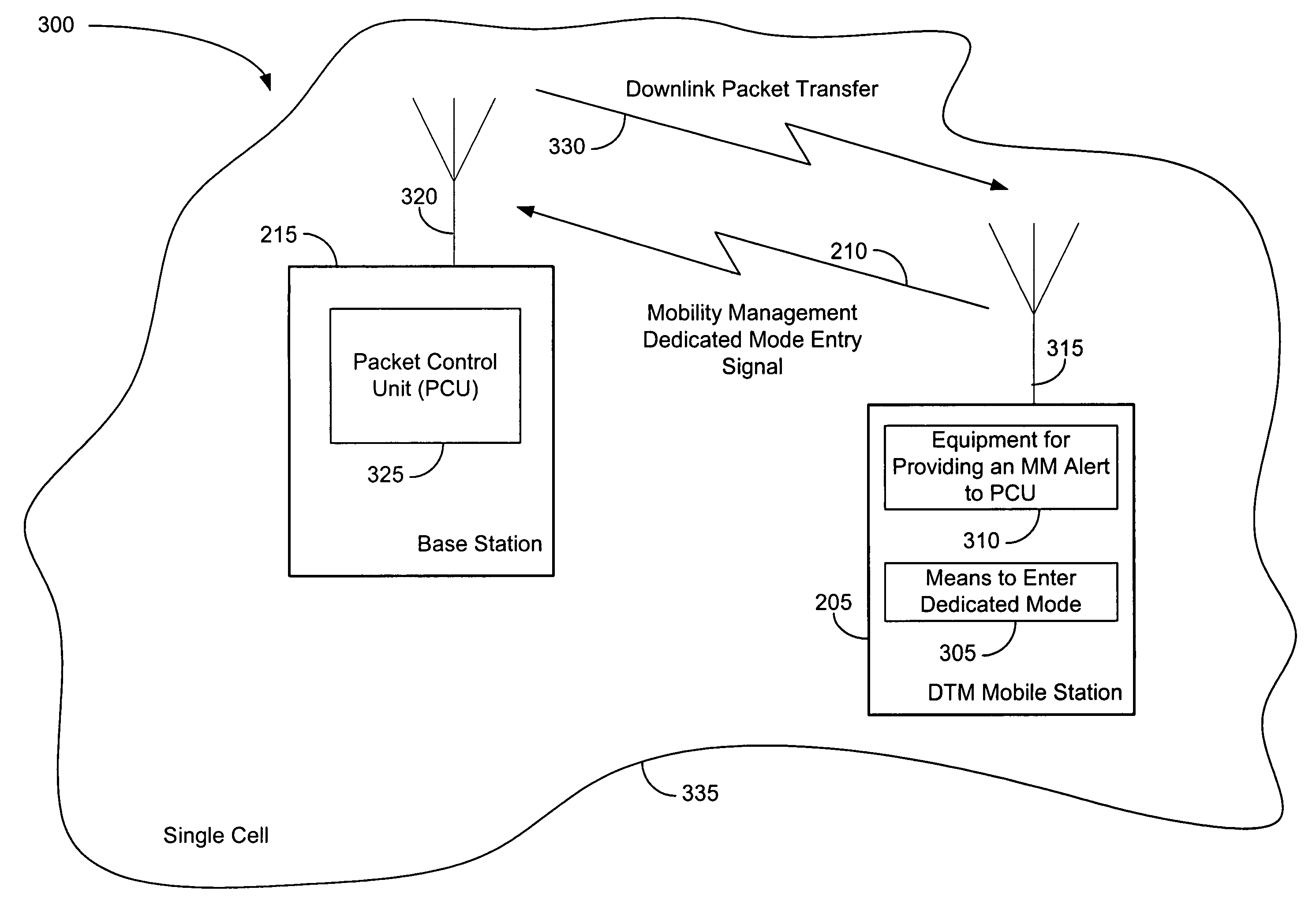
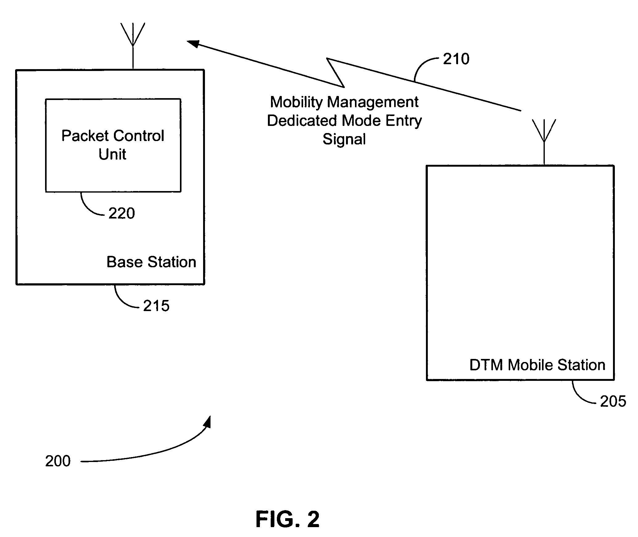
[0022]In dual transfer mode (DTM), the packet control unit (PCU) has to know whether a DTM mobile station (MS) is in dedicated mode when a downlink (DL) packet transfer needs to be established for the MS. This requires a great deal of base station controller (BSC) internal signaling, if the penetration of the DTM mobiles is high. The present invention enables this DTM coordination to only those mobile stations that really are attached to both circuit switched (CS) and packet switched (PS) services, meaning that the BSC internal signaling load can be reduced considerably.
[0023]According to this invention, the base station subsystem (BSS) can utilize mobility management (MM) procedures of GPRS or enhanced GPRS (EGPRS), in order to determine which DTM mobiles are really using the GPRS service during the time when the DTM MS has a CS connection. Mobility management (MM) is a term denoting the mobility functions provided by a Public Land Mobile Network such as GSM. Such functions will include tracking a mobile station as it moves around a network, and ensuring that communication is maintained.

Problems solved by technology

When the use of GSM data services started, it soon became evident that the Circuit Switched (CS) bearer services were not well-suited for certain types of applications with a bursty nature.
The implementation of a “Class A” mobile station would basically require a mobile terminal with two radio parts, resulting in a high development cost, which mobile manufacturers would like to avoid.
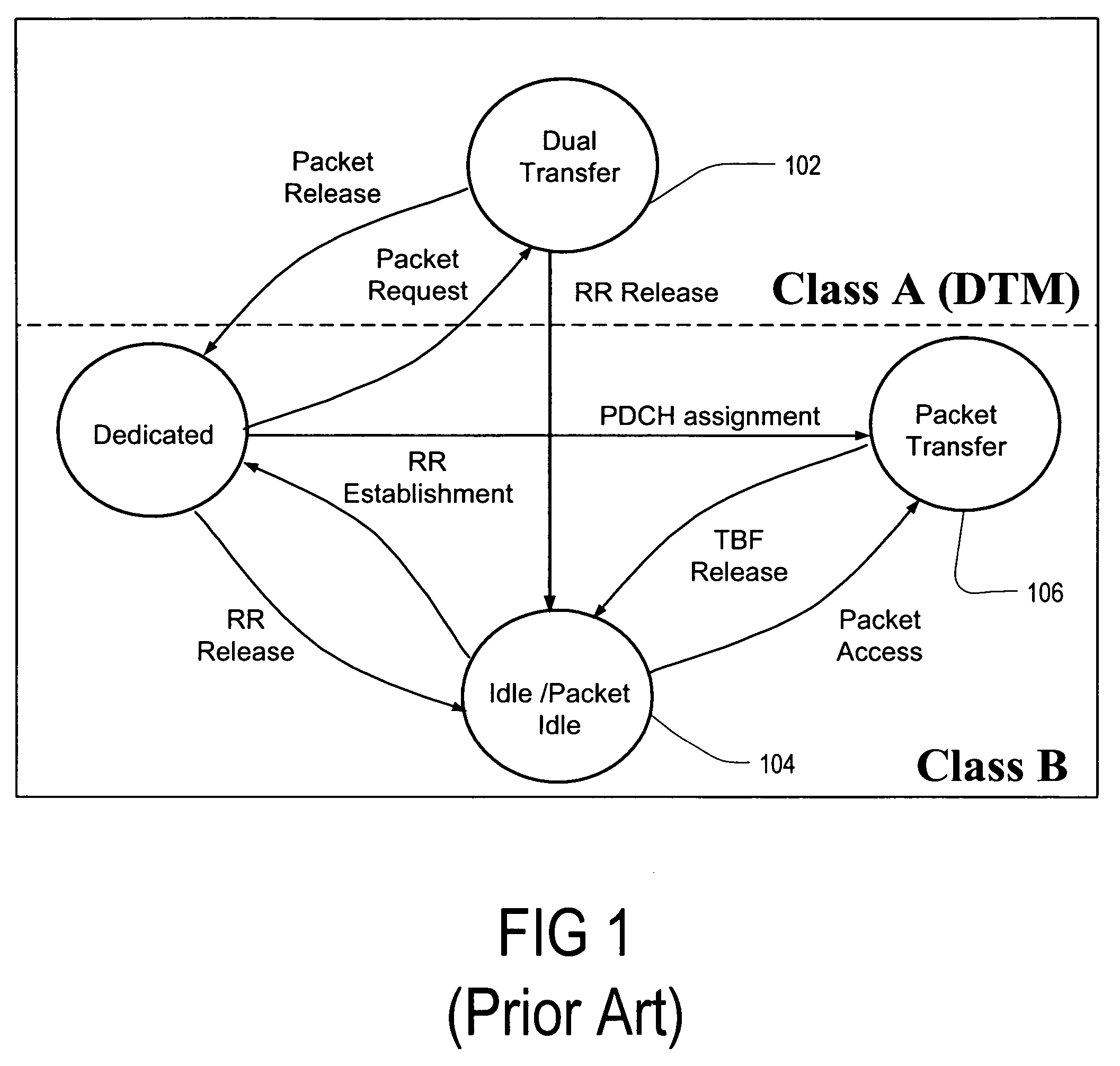
The main problem with this existing technology is that the PCU has to know whether a DTM-capable MS happens to have a CS connection ongoing or not, when there is a need for a PS data transfer.
The problem with the first method (I) is that the PCU has to make such queries very often, because a PS data transfer establishment is a very frequent procedure and also because the PCU cannot really know whether the MS is in dedicated mode or in idle mode.
On the other hand, it is rather improbable that a MS will happen to have a CS connection ongoing when a data packet arrives at the PCU (a typical traffic load generated by a GSM subscriber is 25 mErl, meaning that the subscriber is having a speech connection active only 2.5% of the time).
The problem with the second method (II) is that the DX does not know whether the MS is even attached to the GPRS network.
On the other hand, it is rather improbable that a MS will receive any data packets during the CS connection; most of the mobiles are not even attached to the GPRS network when they are using the CS speech service.
This type of DTM coordination will generate a considerable signaling load within the BSS when the penetration of DTM-capable mobiles increases in the GSM networks.
Unfortunately, MM procedures have not been employed with respect to communications between a DX and PCU, or with respect to an MS's movement in and out of a DTM dedicated mode, which of course can occur even when an MS is perfectly still (i.e. not changing position).
Another problem with the DTM functionality is that when the MS needs to establish a CS connection (e.g. a speech call) when it has active packet data transfer ongoing, the MS releases the packet connection without any signaling to the network, and establishes the CS connection in the random access control channel (RACH).

Method used


Image

  • Method and system of enhanced dual transfer mode using mobility management
  • Method and system of enhanced dual transfer mode using mobility management
  • Method and system of enhanced dual transfer mode using mobility management

Examples


case 1

[0041] The MS establishes a CS connection while being in MM Ready state. In this case the MS shall use one of the new procedures described above. This will trigger a DTM coordination message that is sent from the DX to the PCU. Based on this message the PCU is able to detect that the MS is having a CS connection when the PCU receives a request to establish a PS data transfer for the MS in DL direction.

case 2

[0042] The MS establishes a CS connection while being in MM Standby state. In this case the MS does not perform any DTM-specific procedure and the PCU is not informed about the MS. Note that in this case the PCU does not need to know the mode of the MS because the GPRS core network cannot send data packets for the MS without a PS paging procedure. This is because the MS is in MM Standby state.

case 3

[0043] The MS moves from MM Standby state to MM Ready state during the CS connection. Such a change in the MM state is triggered only if the MS transmits a data packet to the network. In this case the MS has to apply a DTM-specific procedure (a GTTP message or a request for DTM call establishment). This will trigger a DTM coordination message that is sent from the DX to the PCU. Based on this message the PCU is able to detect that the MS is having a CS connection when the PCU receives a request to establish a PS data transfer for the MS in DL direction.


PUM


Abstract

A method, system, and mobile station are presented for informing a packet control unit (PCU) whether the dual transfer mode (DTM) capable mobile station has an ongoing circuit switched connection and is in dedicated mode. The packet control unit will typically be located at a base station. Upon entering the dedicated mode, the mobile station alerts the PCU of entry into the dedicated mode, using a mobility management (MM) procedure. This mobility management procedure is utilized for alerting the PCU about the dedicated mode, regardless of physical movement of the mobile station such as movement from one cell to another.

Description

CROSS-REFERENCE TO RELATED APPLICATION[0001]This application claims priority to U.S. provisional application 60 / 580,204 filed May 27, 2005.FIELD OF THE INVENTION[0002]The present invention relates to wireless telecommunication, and in particular to a mobile station that can communicate in a packet switched environment as well as a circuit switched environment.BACKGROUND OF THE INVENTION[0003]The present invention relates to wireless communication devices such as mobile phones. The first Global System for Mobile (GSM) communication networks were designed for voice services rather than for data services. When the use of GSM data services started, it soon became evident that the Circuit Switched (CS) bearer services were not well-suited for certain types of applications with a bursty nature. Therefore the new Packet Switched (PS) data transmission service GPRS (General Packet Radio Service) was developed for packet services. GPRS is a packet radio network utilizing the GSM network, and...

Claims


Application Information

Patent Timeline
Patent Type & Authority Patents(United States)
IPC IPC(8): H04Q7/00H04B7/212H04L12/56H04W24/00H04W76/04H04W88/06H04W92/10
CPCH04W76/046H04W88/06H04W24/00H04W76/27H04W8/00
Inventor GRONBERG, PETRIKANGAS, ANTTI O.
Owner NOKIA TECH OY
Learn More