Characterization of co-channel interference in a wireless communication system, in particular a cellular radio communication system

a wireless communication system and co-channel interference technology, applied in the field of wireless communication systems, can solve the problems of not having a centralized control of interference coordination, high computation load, and dealing separately with each source, so as to reduce the signalling load, accurate characterization, and reduce the effect of signalling load

Active Publication Date: 2010-06-24
TELECOM ITALIA SPA
View PDF24 Cites 23 Cited by
  • Summary
  • Abstract
  • Description
  • Claims
  • Application Information

AI Technical Summary

Benefits of technology

[0014]The objective of the present invention is therefore to provide a methodology which can alleviate at least some of the above cited drawbacks, and in particular which allows uplink interference characterization to be performed with simple algorithms and light computational and signalling load.
[0018]Moreover, another aspect of the present invention is related to the reduction of signalling load between transceiver stations by grouping the user equipments served by a given transceiver station according to a given grouping criterion with respect to a given interfered neighbouring transceiver station, so that only the information concerning the uplink co-channel interference from each group or from a subset of all groups is signalled.
[0020]Furthermore, grouping of the user equipments in the characterization of the uplink co-channel interference allows to reduce the signalling load between transceiver stations.
[0021]Accordingly, the present invention provides an accurate characterization of co-channel uplink interference in a wireless communication system, which in turn allows to manage interference control and mitigation in a very efficient and performant way.

Problems solved by technology

As such, it is not expected to have in LTE a centralized control of interference coordination.
Such a potentially substantial number of interference sources implies that dealing separately with each source requires a very high signalling load and computation load.

Method used


Image

  • Characterization of co-channel interference in a wireless communication system, in particular a cellular radio communication system
  • Characterization of co-channel interference in a wireless communication system, in particular a cellular radio communication system
  • Characterization of co-channel interference in a wireless communication system, in particular a cellular radio communication system

Examples


Embodiment Construction

[0025]The following description is presented to enable a person skilled in the art to make and use the invention. Various modifications to the embodiments will be readily apparent to those skilled in the art, and the generic principles herein may be applied to other embodiments and applications without departing from the scope of the present invention. Thus, the present invention is not intended to be limited to the embodiments shown, but is to be accorded the widest scope consistent with the principles and features disclosed herein and defined in the attached description and claims.

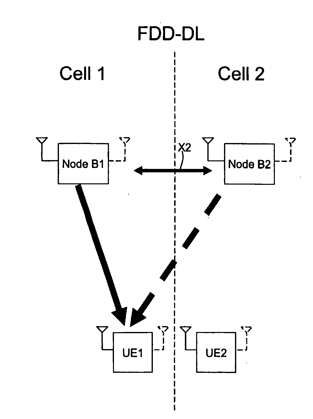
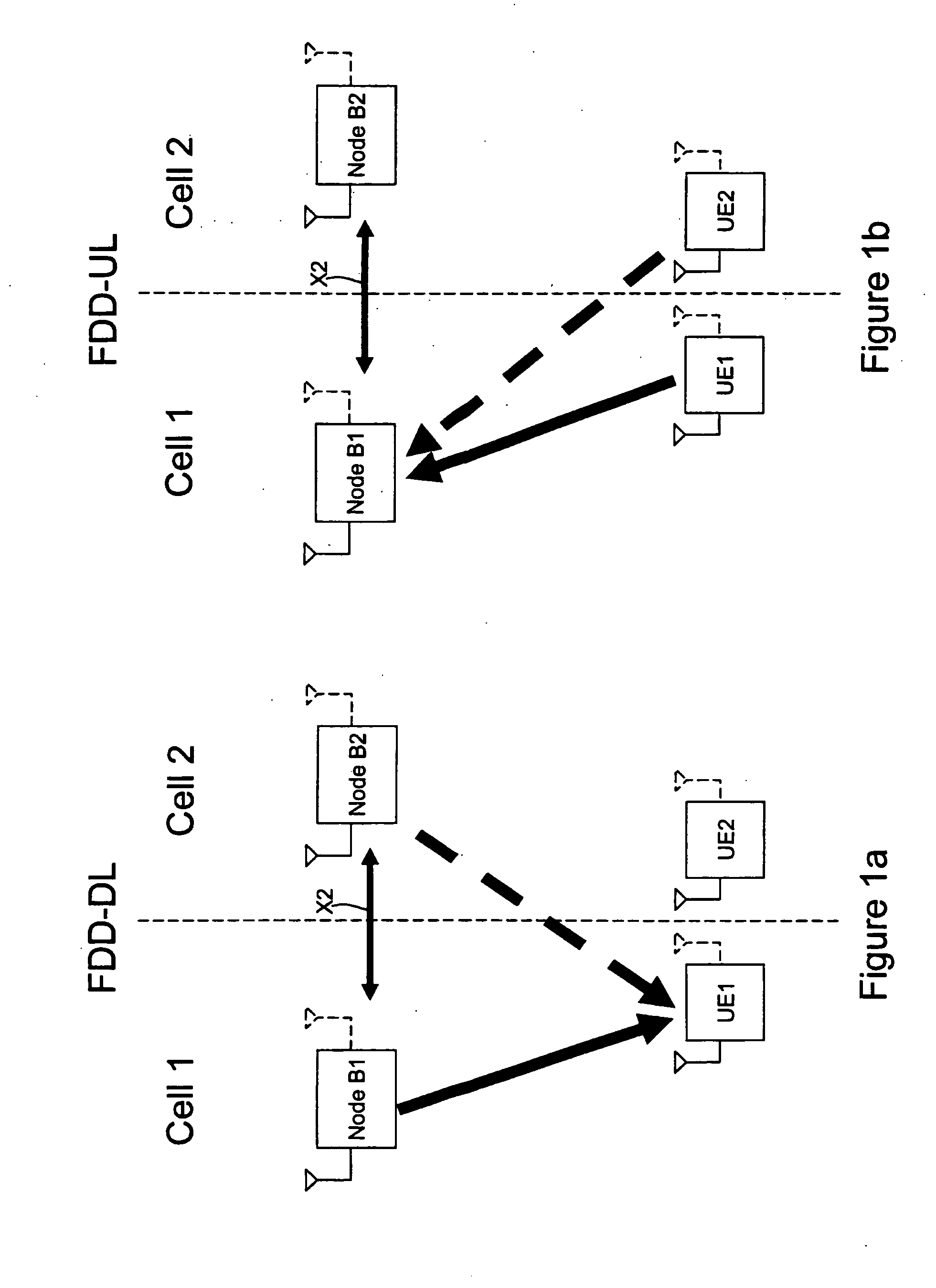
[0026]Additionally, in the following, without losing generality, specific reference will be made to a 3GPP LTE cellular radio communication system, remaining clear that the present invention can also be applied to other type of cellular or non-cellular systems such as WiMAX or WLANs. For this reason, when referring to a transceiver station being part of the network infrastructure, the terminology “Node B...


PUM


Abstract

A method for characterizing interference in a radio communication system including a plurality of user equipment communicating with transceiver stations, includes: determining quantities indicative of interference (attenuation or power) experienced by a transceiver station interfered by interfering user equipment; and exchanging between transceiver stations information based on these quantities and concerning interference from the interfering user equipment. In particular, the user equipment is in communication with respective serving transceiver stations, and exchanging includes sending from the serving transceiver stations to the interfered transceiver stations information concerning interference from user equipment served by the serving transceiver stations and interfering with the interfered transceiver stations. The method further includes grouping, by the serving transceiver station, the interfering user equipment according to a given grouping criterion in order to form groups thereof.

Description

TECHNICAL FIELD OF THE INVENTION[0001]The present invention relates in general to wireless communication systems, and more specifically to co-channel interference characterization, feedback reduction and interference mitigation in cellular and non-cellular radio communication systems.[0002]In particular, cellular radio communication systems where the present invention may find advantageous, but not limitative application, are for example the so-called beyond-3G (3rd Generation) cellular radio communication systems, i.e. new generation cellular radio communication systems having a wider transmission bandwidth than 3G cellular radio communication systems, such as for example those known as Third Generation Partnership Project Long Term Evolution (3GPP LTE) cellular radio communication systems.[0003]Non-cellular radio communication systems where the present invention may find advantageous, but not limitative application are for example Wireless Local Area Networks (WLANs), and in parti...

Claims


Application Information

Patent Timeline
Patent Type & Authority Applications(United States)
IPC IPC(8): H04B17/00H04W24/00H04W28/04
CPCH04B17/005H04L27/2602H04B17/345H04W28/04H04B17/24H04W24/00H04W28/0236H04W24/08H04W72/0453H04B7/0456
Inventor BARBERIS, SERGIOPRIOTTI, PAOLO
Owner TELECOM ITALIA SPA
Why Eureka
Try Eureka