Eureka AIR delivers breakthrough ideas for toughest innovation challenges, trusted by R&D personnel around the world.

Crown molding

a crown molding and crown molding technology, applied in the field of crown molding, can solve the problems of labor-intensive installation, high cost, and high labor intensity of skilled carpenters, and achieve the effect of simple installation

Active Publication Date: 2008-11-18
SPEXCO
View PDF21 Cites 18 Cited by
  • Summary
  • Abstract
  • Description
  • Claims
  • Application Information

AI Technical Summary

Benefits of technology

[0012]Still another object of the present invention is to provide a crown molding system that includes straight members and, ninety and forty five degree corner members that receive ends of the straight members fitted thereto receive joint compound applied thereover and along the joints, that can be sanded and / or left textured, to receive paint applied thereto, providing a versatile system for covering the walls and ceiling junctions.
[0013]Still another object of the present invention is to provide a crown molding system that is simple to install by even an unskilled person, includes pre-fabricated corners and angle members allowing the system to be installed with no compound miter cuts and will provide a room with crown molding of the same or better appearance to one constructed by a skilled carpenter.

Problems solved by technology

Such installation is labor intensive, requires a skilled carpenter and, accordingly, has been very expensive.

Method used


Image

  • Crown molding
  • Crown molding
  • Crown molding

Examples


Embodiment Construction

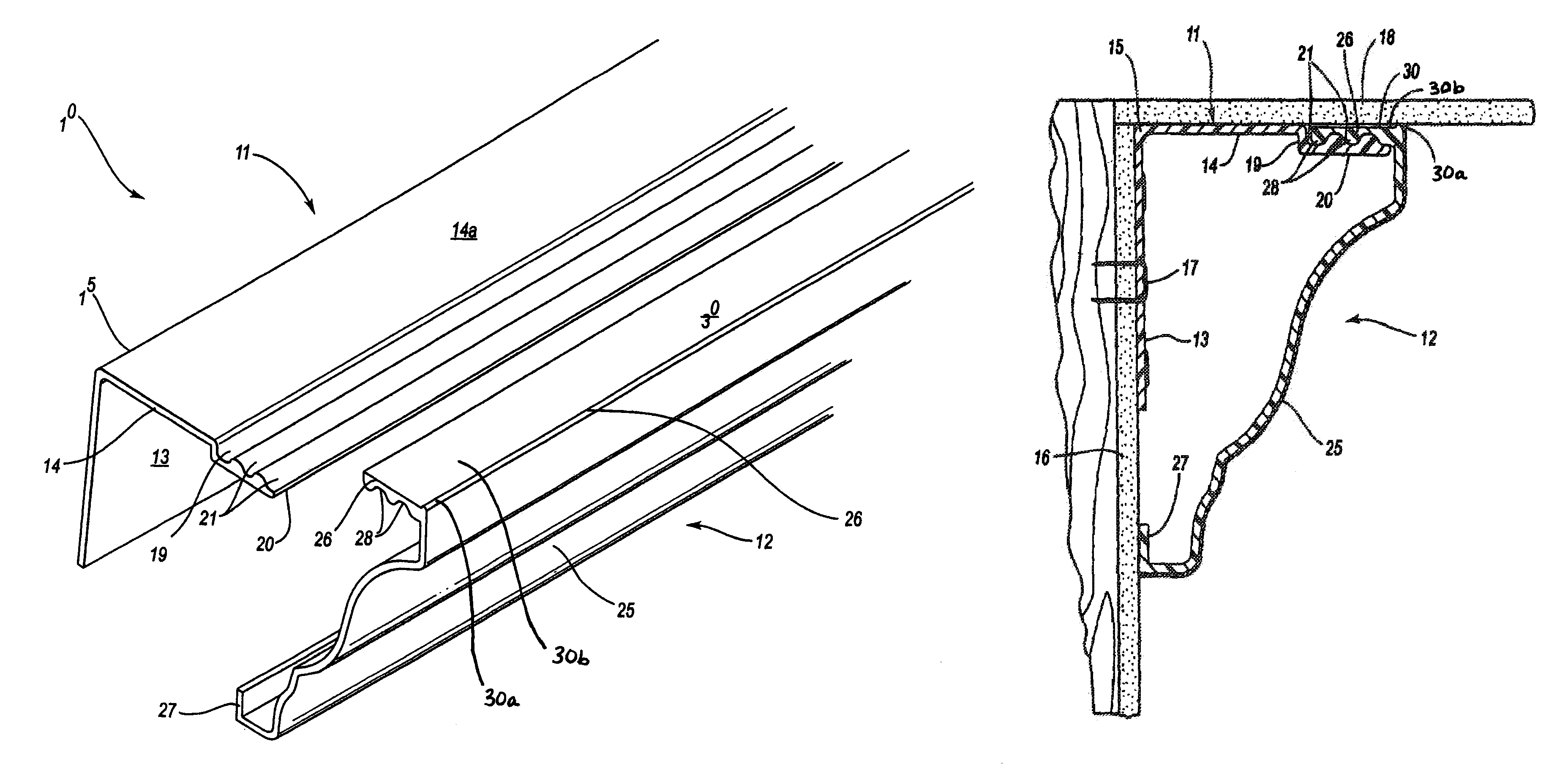
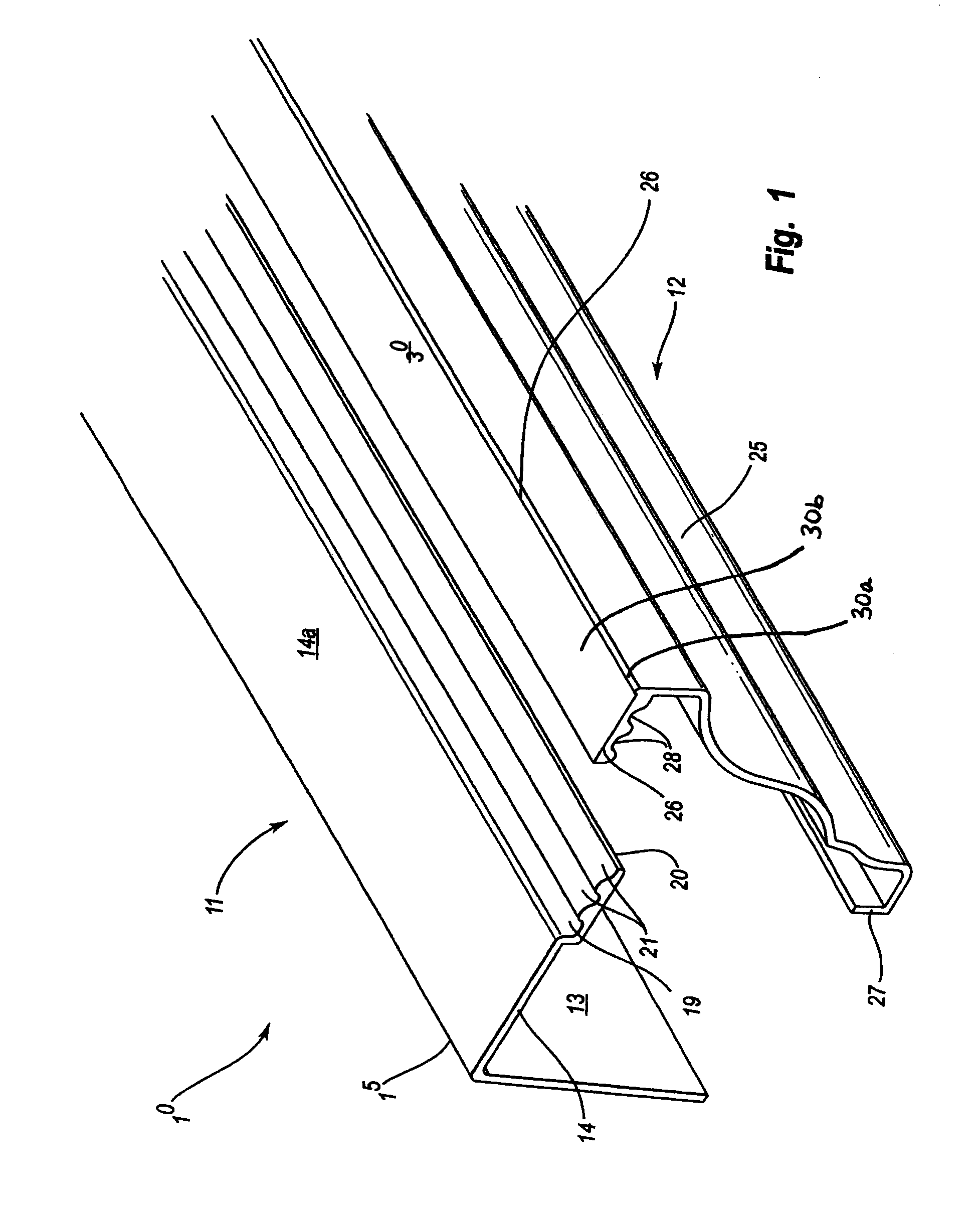
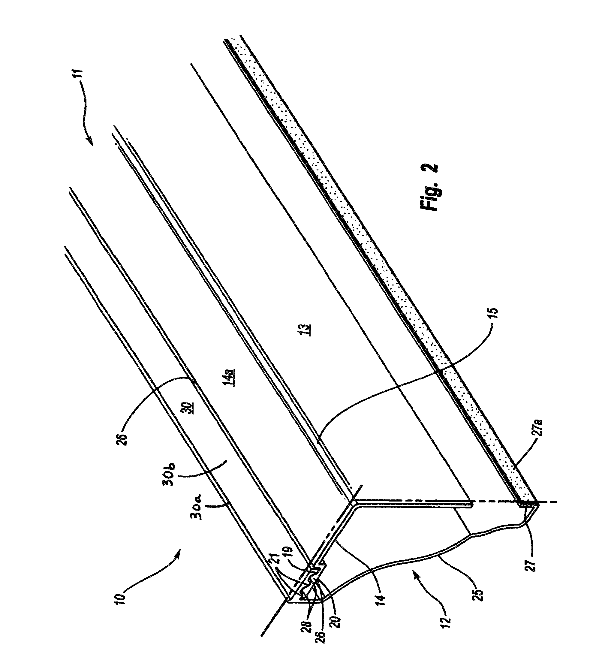
[0030]The invention, as is hereinafter described, relates to crown mold and crown molding systems that have heretofore been installed by skilled carpenters. Whereas, the present invention provides extruded plastic components that are preferably formed from a plastic composite material, with an outer crown molding surface to allow the finished crown molding to accept a layer of joint compound, providing a texture thereto, that can be painted or left unpainted. The crown molding of the invention can be easily installed by a non-carpenter having little or minimum experience, who installs the crown molding system so as to provide a finished crown molding that is comparable if not better looking than wood crown moldings as have been carpenter installed.

[0031]A first embodiment of the crown molding 10 of the invention is shown in a frontal perspective view taken from the left side of FIG. 1, that shows an inverted “L” bracket 11, hereinafter referred to as “L” bracket 11, that is aligned ...


PUM


Abstract

A crown molding and system for its use where the crown molding is formed from a specially blended plastic as extrusions to have a roughened surface and consisting of an inverted “L” bracket and a facing crown mold member for each crown molding section. The inverted “L” bracket is formed as a right angle section having right angle legs and is to be attached to a wall at points along its lower leg, with the right angle bend fitting into the wall to ceiling junction, and with the top leg end having a coupling end for connecting to a mount of a facing crown molding member. Which coupling edges are preferably mirror image corrugations that fit over and lock together, and with the facing member ends flanges to contact the wall and ceiling surfaces.

Description

BACKGROUND OF THE INVENTION[0001]1. Field of the Invention[0002]The present invention pertains to crown molding and to crown molding systems for use in new construction and remodeling.[0003]2. Prior Art[0004]Crown molding has historically and is currently manufactured in long wood sections for installation by a carpenter who miter cuts and fits the molding around a ceiling junction with the room walls. Such installation is labor intensive, requires a skilled carpenter and, accordingly, has been very expensive. The invention provides a crown molding that is preferably an extruded plastic inverted “L” bracket mounting members and a facing crown molding section or member that are quickly and easily installed without a need for a skilled or unskilled carpenter. Which installation involves installing an inverted “L” bracket mounting member, as by stapling or nailing it between the wall and ceiling, that includes a top corrugated end that receives a like corrugated end of the facing crown...

Claims


Application Information

Patent Timeline
Patent Type & Authority Patents(United States)
IPC IPC(8): E04F19/04
CPCE04B9/30E04F19/0436E04F19/0463E04F19/0495E04F2019/0413E04F2019/0454
Inventor SPEK, MICHAEL TIMOTHY
Owner SPEXCO
Why Eureka
Eureka Blog
Learn More