
Induction regulator for an internal combustion engine

a technology for internal combustion engines and induction regulators, which is applied in the direction of combustion air/fuel air treatment, fuel thermal treatment, air intakes for fuel, etc., can solve the problems of difficult fitting and sealing of many prior art induction regulators are not sufficiently effective, etc., and achieve the effect of alleviating one or mor

Inactive Publication Date: 2008-11-18
KENNEDY
View PDF16 Cites 2 Cited by
  • Summary
  • Abstract
  • Description
  • Claims
  • Application Information

AI Technical Summary

Benefits of technology

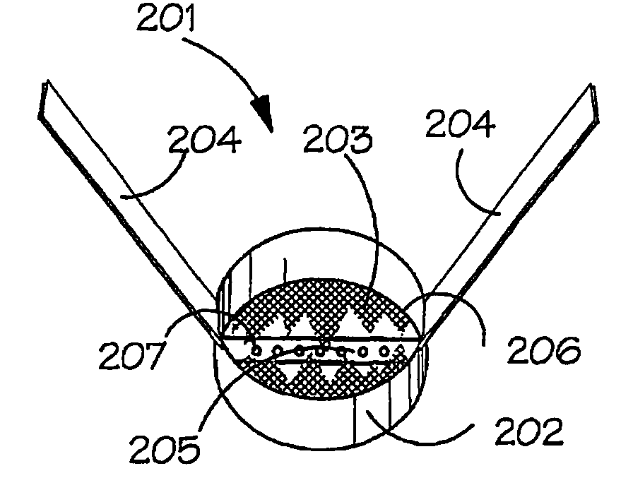
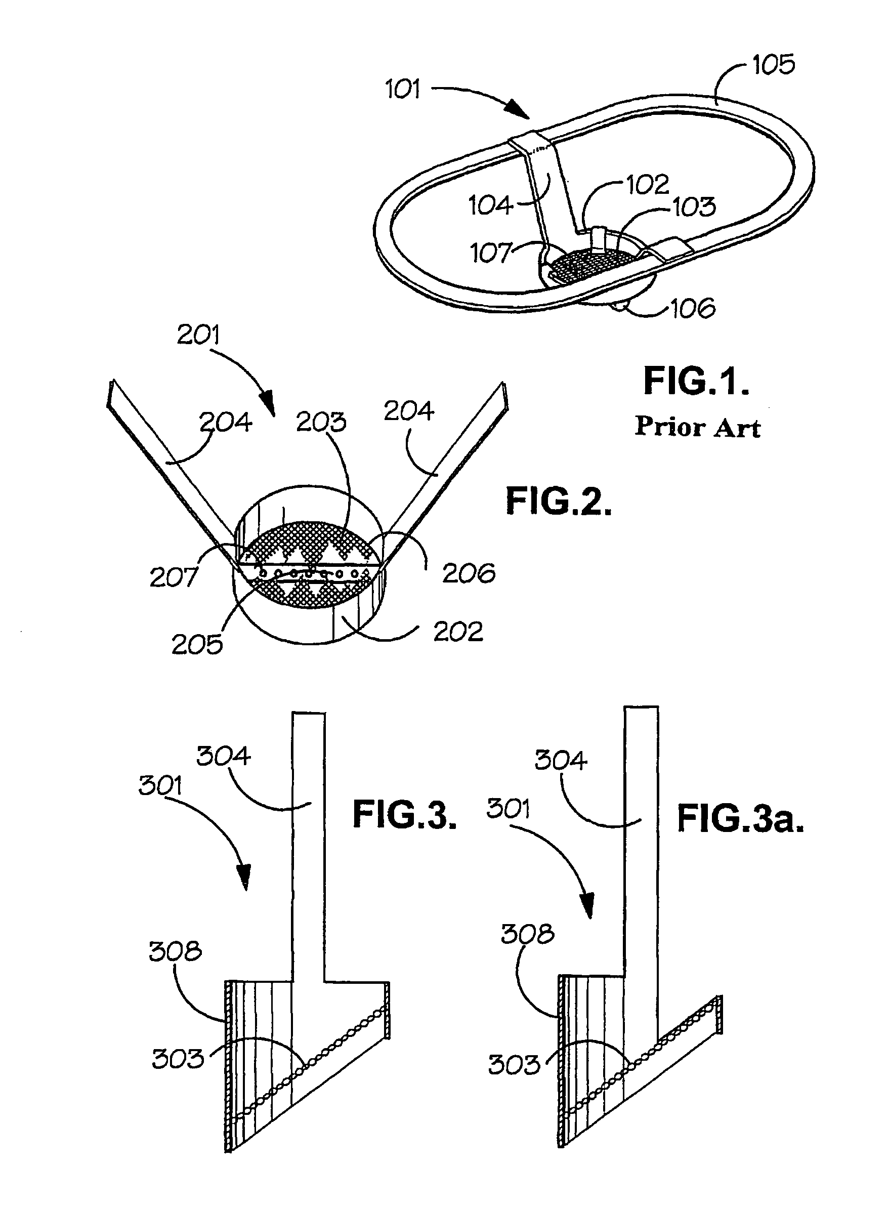
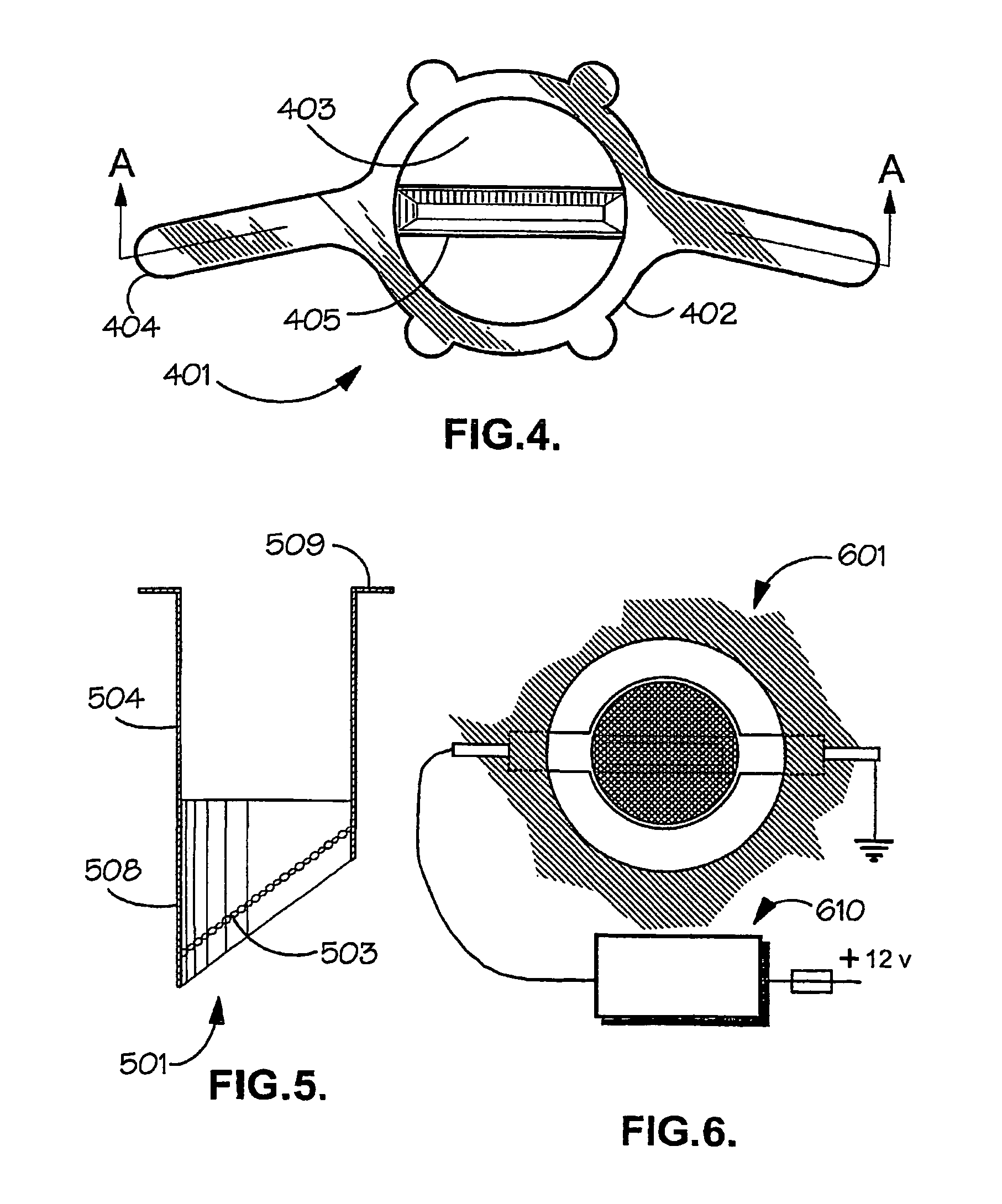
"The present invention provides an improvement to an induction regulator for an internal combustion engine. The invention provides an induction regulator with a perforated element for allowing the passage of fuel / air mixture therethrough and an open-topped reservoir for retaining excess unvaporized fuel. The perforations in the open-topped reservoir enhance the swirling motion of the fuel / air mixture when passing through and over the regulator, improving atomization / vaporization of the fuel and engine performance. The invention also provides an induction regulator with a skirt at one side of the perforated element, which improves swirling motion and engine performance. The invention further provides an induction regulator with means for mounting the perforated element in the inlet manifold of an engine and means for heating the perforated element. These improvements make the regulator easier to fit in an optimum fashion and prevent air / fuel leakage."

Problems solved by technology

For example, many prior art induction regulators are not sufficiently effective in promoting swirling promotion of the fuel / air mixture when passing therethrough.
The performance of some prior art induction regulators is not optimized during engine start up procedure and for the first few minutes thereafter before the engine warms up.
Some prior art induction regulators are difficult to fit and seal and some cannot be fitted to a multi-point system.

Method used


Image

  • Induction regulator for an internal combustion engine
  • Induction regulator for an internal combustion engine
  • Induction regulator for an internal combustion engine

Examples


Embodiment Construction

[0047]With reference to FIG. 1, a prior art induction regulator 101 for disposal in the inlet manifold of an engine downstream of a carburettor is shown. The regulator comprises frame 102 which bounds metal gauze 103 and which acts to support gauze 103 around its periphery. Two strips of metal 104 extend from frame 102. Strips 104 are secured at their ends remote from frame 102 to a continuous strip of metal 105. Continuous strips 105 can be clamped between the flanges of the inlet manifold and of the carburettor in use of the regulator. Frame 102 is disposed at an angle to strips 5 and preferably at an angle of about 72°. An open-topped reservoir is secured to frame 102 and its edges surrounding the open top are formed with lip 107 which serves to support gauze 103. Reservoir 106 is elongate and is positioned centrally across the width of gauze 103, between the points where strips connect to frame 102. Gauze 103 extends over the top of reservoir 106. The reservoir serves as a drip ...


PUM


Abstract

The invention relates to an induction regulator (201) for an internal combustion engine which comprises one or more features selected from: at least one perforated element (203) for allowing the passage of fuel / air mixture therethrough, at least one open-topped reservoir (205) for retaining excess unvapourised fuel and means (204) for mounting the regulator in the inlet manifold of an engine, the open-topped reservoir (205) comprising a series of perforations (207) therein; at least one perforated element for allowing the passage of fuel / air mixture therethrough, means for mounting the perforated element in the inlet manifold of an engine and the means (510) for heating the perforated element; and a propeller and means for mounting the propeller (703, 803, 903) in the inlet manifold of an engine.

Description

CROSS-REFERENCES TO RELATED APPLICATIONS[0001]This application is a continuation application which claims benefit of U.S. patent application Ser. No. 10 / 474,945 filed Oct. 15, 2003, now U.S. Pat. No. 7,171,959 entitled “Induction Regulator For An Internal Combustion Engine”, which is a 371 application of PCT / GB02 / 01831 filed Apr. 19, 2002, which claims benefit of U.K. Patent Application No. 0109623.9 filed Apr. 19, 2001 and U.K. Patent Application No. 0114573.9 filed Jun. 15, 2001, which are hereby incorporated by reference.STATEMENT REGARDING FEDERALLY SPONSORED RESEARCH OR DEVELOPMENT[0002]Not ApplicableREFERENCE TO SEQUENCE LISTING OR COMPUTER PROGRAM LISTING APPENDIX[0003]Not ApplicableBACKGROUND OF THE INVENTION[0004]The present invention relates to an induction regulator for an internal combustion engine.[0005]An induction regulator is known from UK-A-2099074 which is designed to compensate for irregularities in the supply to and demand for fuel from the engine and thus leads ...

Claims


Application Information

Patent Timeline
Patent Type & Authority Patents(United States)
IPC IPC(8): F02M29/04F02M29/02F02M31/04F02M31/135F02M35/10
CPCF02M29/04Y02T10/146Y02T10/12
Inventor KENNEDY
Owner KENNEDY
Learn More