Seat belt pretensioner

a seat belt and pretensioner technology, applied in the direction of safety belts, pedestrian/occupant safety arrangements, vehicular safety arrangements, etc., can solve the problems of inability to meet safety standards, failure with very dire consequences for seat occupants, and inability to take up sufficient slack in the belt webbing alon

Inactive Publication Date: 2008-11-18
KEY SAFETY SYST
View PDF23 Cites 22 Cited by
  • Summary
  • Abstract
  • Description
  • Claims
  • Application Information

AI Technical Summary

Problems solved by technology

While this seat belt tightening arrangement operates by pulling the belt webbing in a forward direction, with respect to vehicle travel, there is a recognized aversion to a vehicle seat moving at all during a crash because if the crash is severe enough the abutment arrangement could fail with very dire consequences for the seat occupant.
The pretensioning performance of these so-called sill pretensioners has been extremely limited because of the limits of space in this area of the vehicle, and they have not hitherto been capable alone of taking up sufficient slack in the belt webbing to satisfy safety standards.

Method used


Image

  • Seat belt pretensioner
  • Seat belt pretensioner
  • Seat belt pretensioner

Examples


Embodiment Construction

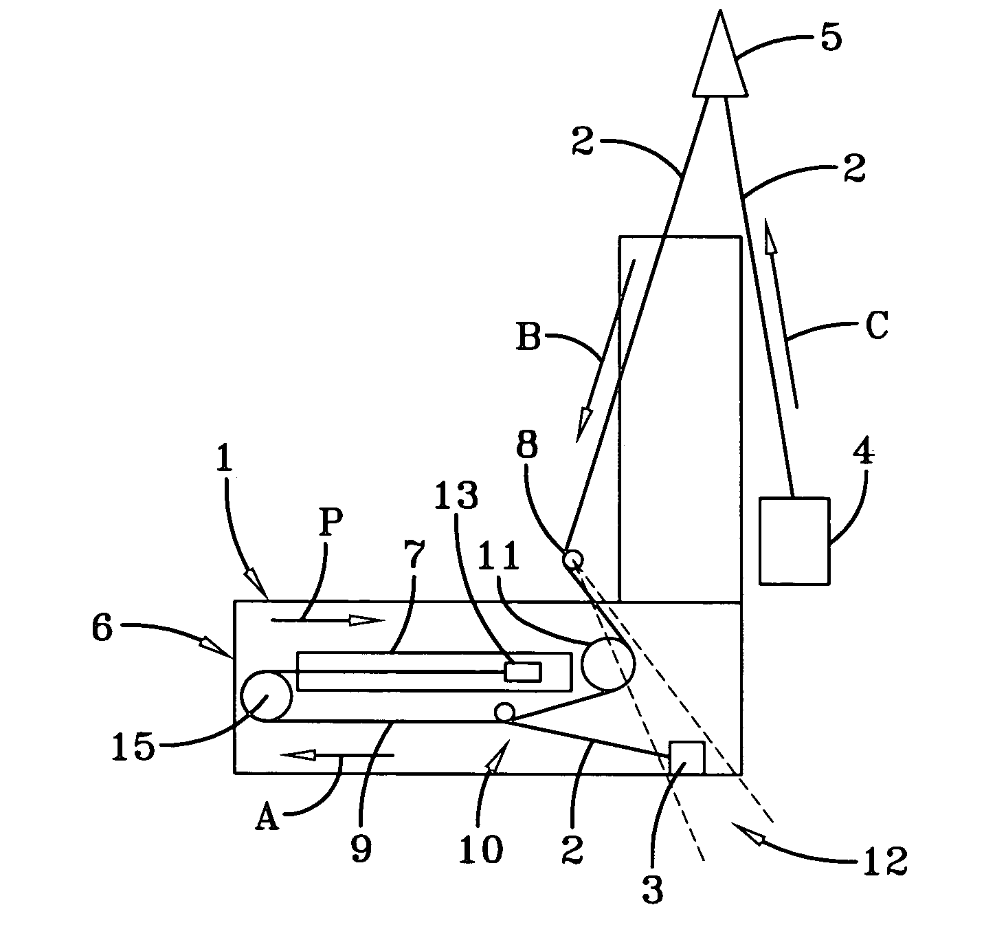
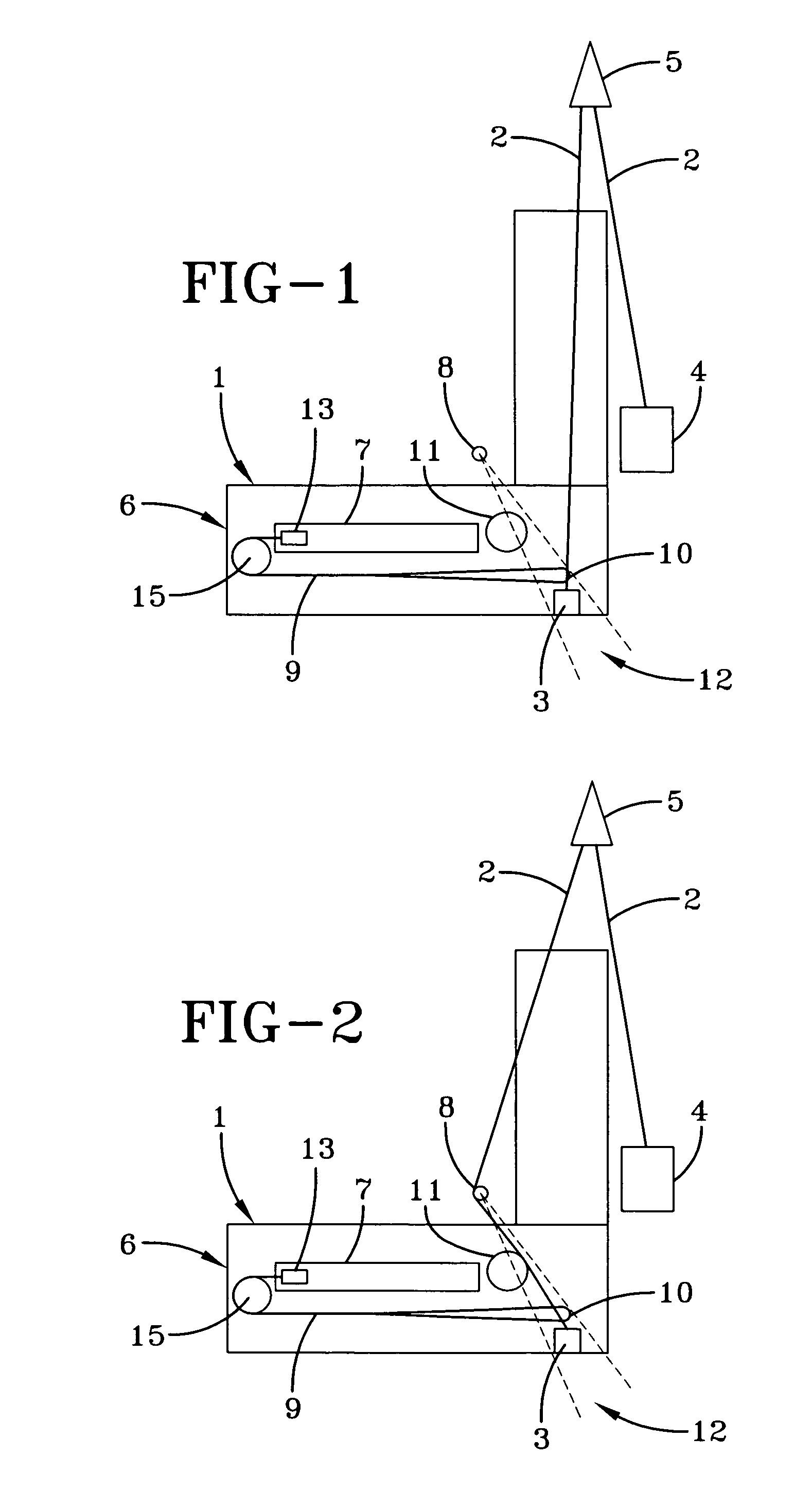
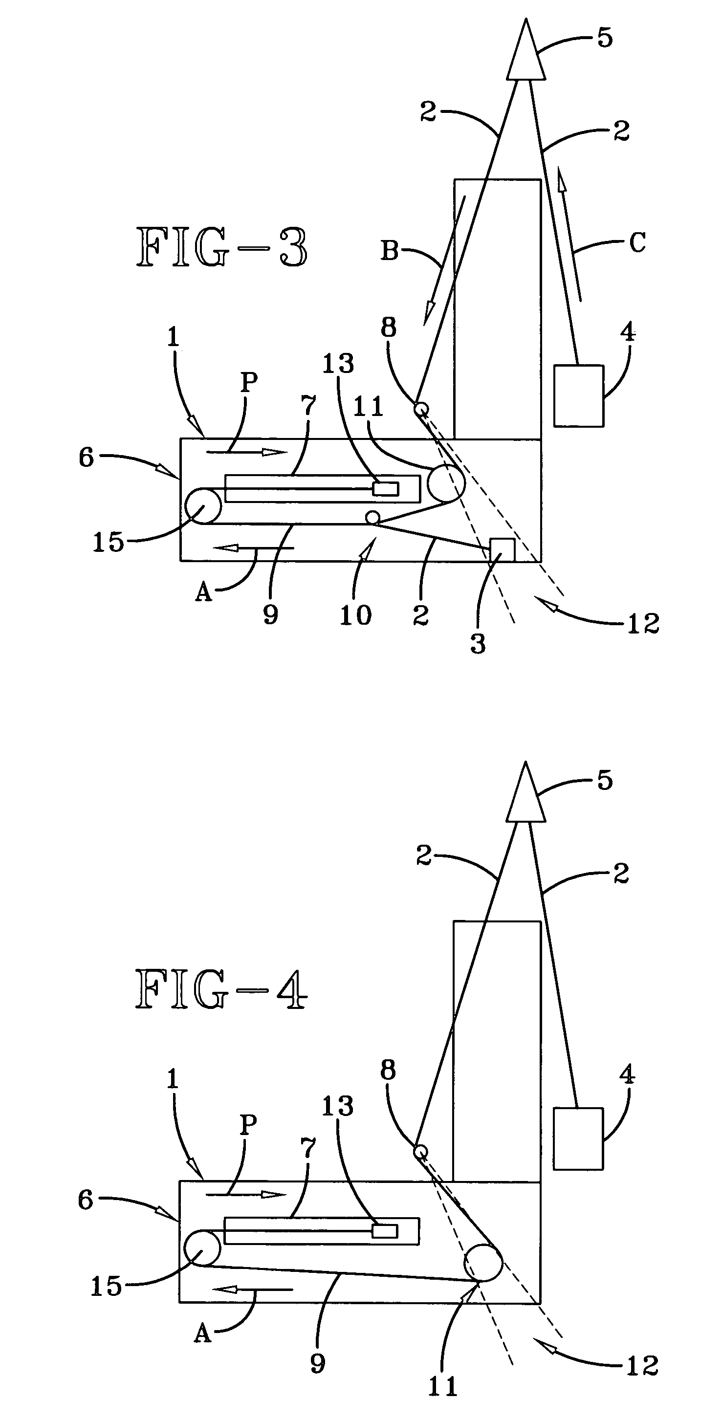
[0021]As used throughout this description, and in the claims, terms such as “forward” and “rearward”, “front” and “back” and similar terms are understood to refer to directions with respect to the front and rear of a vehicle in which the seat belt pretensioning apparatus of the invention is installed. Similarly, terms such as “above” and “below”, and “higher” and “lower” are understood to be relative to the normal orientation of the top and bottom of a passenger compartment of a vehicle in which the seat belt pretensioning apparatus of the invention is installed.

[0022]In all the figures a vehicle seat 1 is shown fitted with a seat belt in known manner. The seat belt comprises seat belt webbing 2, one end of which is attached to, or connected in a load bearing manner 3, to a load bearing part of the vehicle. It may be anchored to a chassis member, part of the floor of the vehicle, to a doorsill or to part of the seat 1 or the seat rail to which the seat frame is slideably attached. P...


PUM


Abstract

A pretensioning apparatus for seat belt webbing is located in the vicinity of a belt anchor end of a three-point vehicle safety restraint seat belt. The pretensioning apparatus has a fixed member in the form of a tubular member that may be anchored to a vehicle seat at the belt anchor side of the vehicle. A movable member in the form of a piston is connected to the webbing in the region of the belt anchor end. A means is provided for moving the movable member relative to the fixed member in a generally horizontal direction, to move the seat belt webbing in a pretensioning direction in response to a signal from a crash sensor. A webbing guide is fixed to the seat to provide an effective anchorage point spaced from the belt anchor end of the webbing under pretensioning conditions.

Description

FIELD OF THE INVENTION[0001]The present invention relates to a seat belt pretensioner.BACKGROUND OF THE INVENTION[0002]A typical seat belt comprises a length of belt webbing connected at three points to load bearing parts of a vehicle. Typically one end of the webbing is attached to a belt anchor that is bolted to a load bearing longitudinally extending chassis member on one side of a seat between the seat and the adjacent door. The webbing is arranged to pass laterally across the hips of a seat occupant to a buckle mechanism fixed to the vehicle on the opposite side of the seat, and then diagonally across the torso of the seat occupant, via a webbing guide, to a retractor mounted on the B pillar adjacent the door. A buckle mechanism engages a buckle tongue that is attached to the webbing in a sliding manner.[0003]The retractor fitted at the pillar end of the webbing increases the comfort of the seat occupant restrained by the belt by allowing the webbing to pay out under relatively...

Claims


Application Information

Patent Timeline
Patent Type & Authority Patents(United States)
IPC IPC(8): B60R22/46
CPCB60R22/1951B60R22/26B60R2022/263B60R22/46
Inventor BELL, JOHN FORSTER
Owner KEY SAFETY SYST
Why Eureka
Try Eureka