Ceramic matrix composite turbine engine vane

a composite and turbine engine technology, applied in the direction of wind motors with perpendicular air flow, machines/engines, climate sustainability, etc., can solve the problems of large pressure difference through the shell, high mechanical stress, and the effect of over-design maxima

Active Publication Date: 2008-11-18
TECH UNITED
View PDF16 Cites 79 Cited by
  • Summary
  • Abstract
  • Description
  • Claims
  • Application Information

AI Technical Summary

Problems solved by technology

The thin shell works well to control the thermal stress, but it also leads to high mechanical stress resulting from the pressure differential between the shell interior and the external gas flow.
This creates a large pressure difference through the shell.
These stresses may exceed design maxima, particularly, at the leading edge.
Although they can be easily provided in all-metal vanes, manufacturing CMC ribs as integral parts of the shell is difficult.
Furthermore, high tensile stress is likely to develop between the relatively cold ribs and hot shells, making such a construction less feasible.
This, unfortunately, drives up the thermal stress.
However, the external airfoil profile is optimized for best aerodynamic performance and could be highly sensitive to any changes.
As a result, only the internal radius can be increased and the available amount of stress reduction is limited.

Method used


Image

  • Ceramic matrix composite turbine engine vane
  • Ceramic matrix composite turbine engine vane
  • Ceramic matrix composite turbine engine vane

Examples


Embodiment Construction

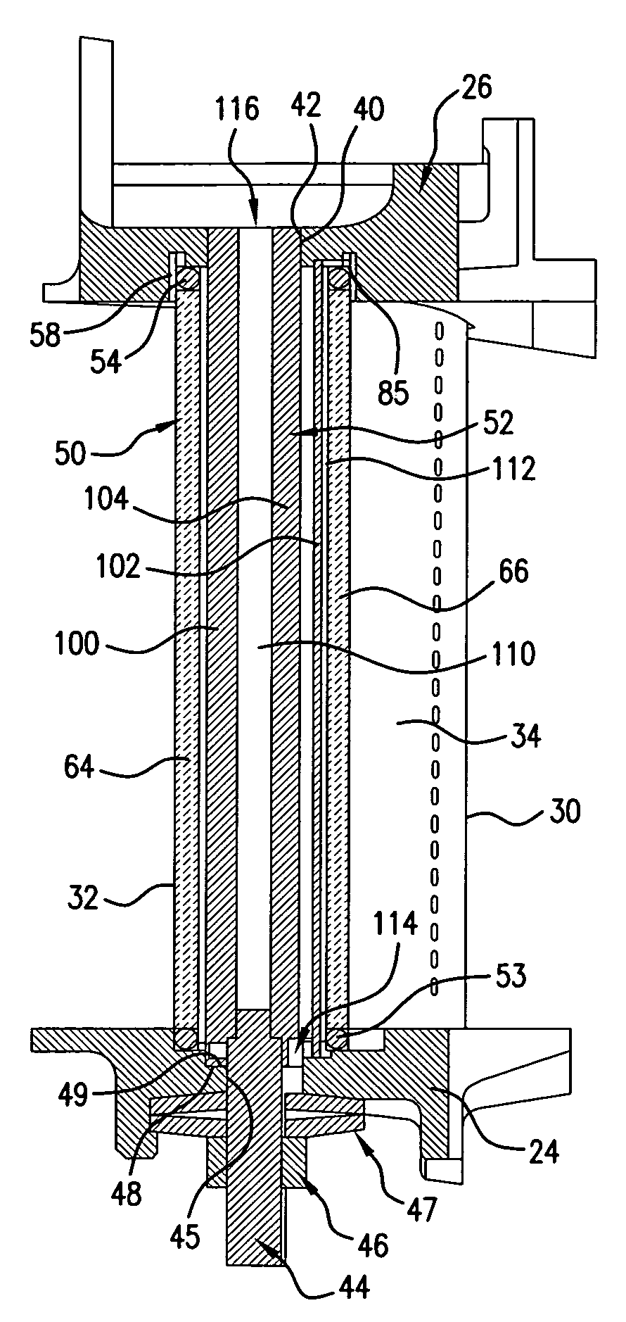
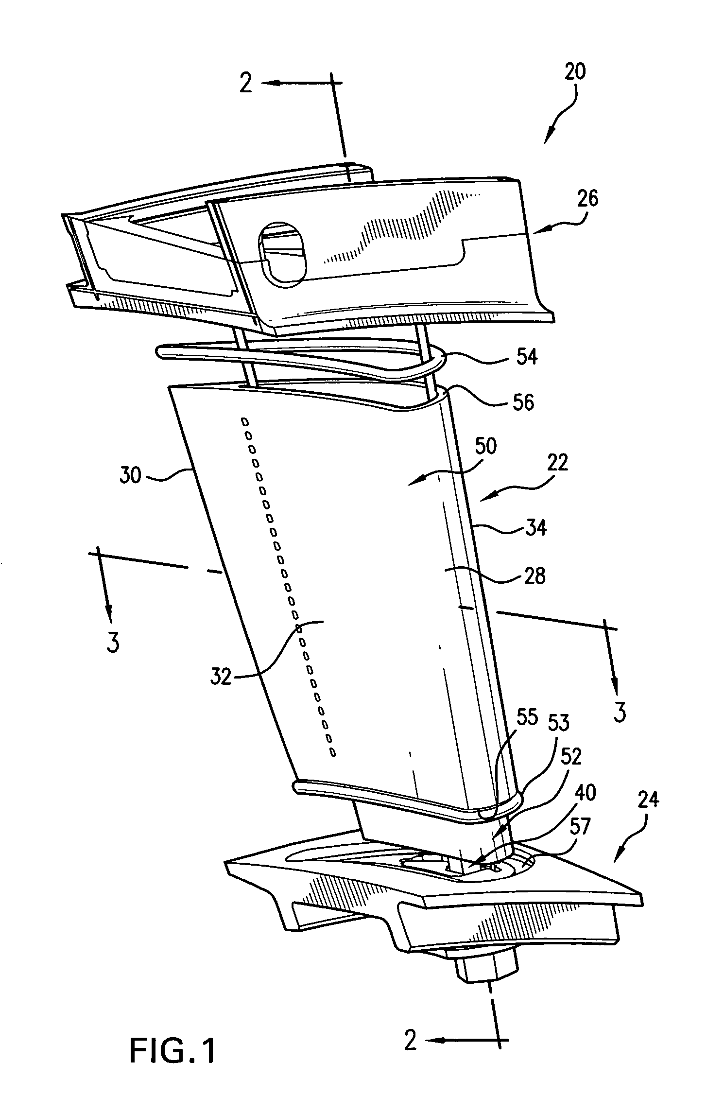
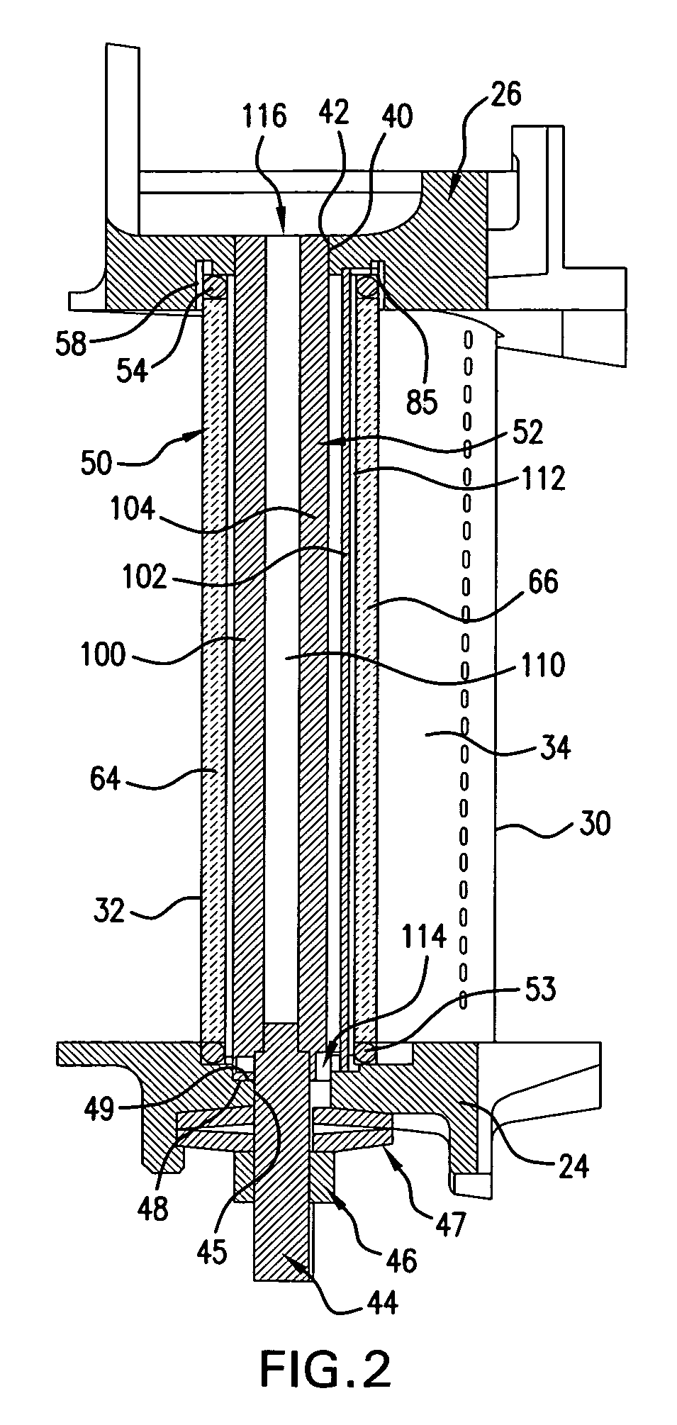
[0024]FIG. 1 shows a vane 20 having an airfoil 22 extending from an inboard end at an inboard platform 24 to an outboard end at an outboard shroud 26. The airfoil 22 has a leading edge 28, a trailing edge 30, and pressure and suction side surfaces 32 and 34 extending between the leading and trailing edges. The exemplary platform and shroud form segments of an annulus so that a circumferential array of such vanes may be assembled with shrouds and platforms sealed / mated edge-to-edge.

[0025]The exemplary vane 20 is an assembly wherein the shroud, platform, and airfoil are separately formed and then secured to each other. FIGS. 1-3 show the airfoil as comprising a thin-walled shell 50 and a structural spar 52 within the shell. Exemplary shell material is a CMC. The shell may be manufactured by various CMC fabrication methods. These typically involve forming a preform of ceramic fiber (e.g., SiC) in the shape of the airfoil (e.g., by weaving or other technique) and infiltrating the prefor...


PUM

PropertyMeasurementUnit
pressureaaaaaaaaaa
pressureaaaaaaaaaa
pressureaaaaaaaaaa

Abstract

A vane has an airfoil shell and a spar within the shell. The vane has an outboard shroud at an outboard end of the shell and an inboard platform at an inboard end of the shell. The spar has a first chamber essentially along the suction side and a second chamber along the pressure side opposite the first chamber.

Description

U.S. GOVERNMENT RIGHTS[0001]The invention was made with U.S. Government support under contract NAS3-01138 awarded by NASA. The U.S. Government has certain rights in the invention.BACKGROUND OF THE INVENTION[0002]The invention relates to turbine engines. More particularly, the invention relates to ceramic matrix composite(CMC) turbine engine vanes.[0003]Ceramic matrix composites have been proposed for the cooled stationary vanes of gas turbine engines. One example is found in U.S. Pat. No. 6,514,046 of Morrision et al.[0004]The high thermal loading on the vanes results in configurations with thin shells to minimize thermal stress, in particular, inter-laminar tensile stress. The thin shell works well to control the thermal stress, but it also leads to high mechanical stress resulting from the pressure differential between the shell interior and the external gas flow.[0005]Whereas the external hot gas pressure drops sharply from the leading edge to the trailing edge, the internal cool...

Claims


Application Information

Patent Timeline
Patent Type & Authority Patents(United States)
IPC IPC(8): F04D29/54
CPCF01D5/147F01D5/18F01D5/282F05D2230/314F05D2300/21F05D2300/2261F05D2300/603Y02T50/60
Inventor SHI, JUNOCHS, STUART S.GREEN, KEVIN E.JARMON, DAVID C.SAHM, MICHAEL K.PRILL, LISA A.
Owner TECH UNITED
Why Eureka
Try Eureka