
Process for the treatment of a hydrocarbon feedstock
a hydrocarbon feedstock and process technology, applied in the direction of hydrocarbon oil cracking process, thermal non-catalytic cracking, etc., can solve the problems of limited hydrogen purity, significant quantity of lpg is evacuated, and the purity of lpg is limited, so as to maximize the recovery of lpg and minimize the loss of lpg
- Summary
- Abstract
- Description
- Claims
- Application Information
AI Technical Summary
Benefits of technology
Problems solved by technology
Method used
Image

Examples
example 1
for Comparison:
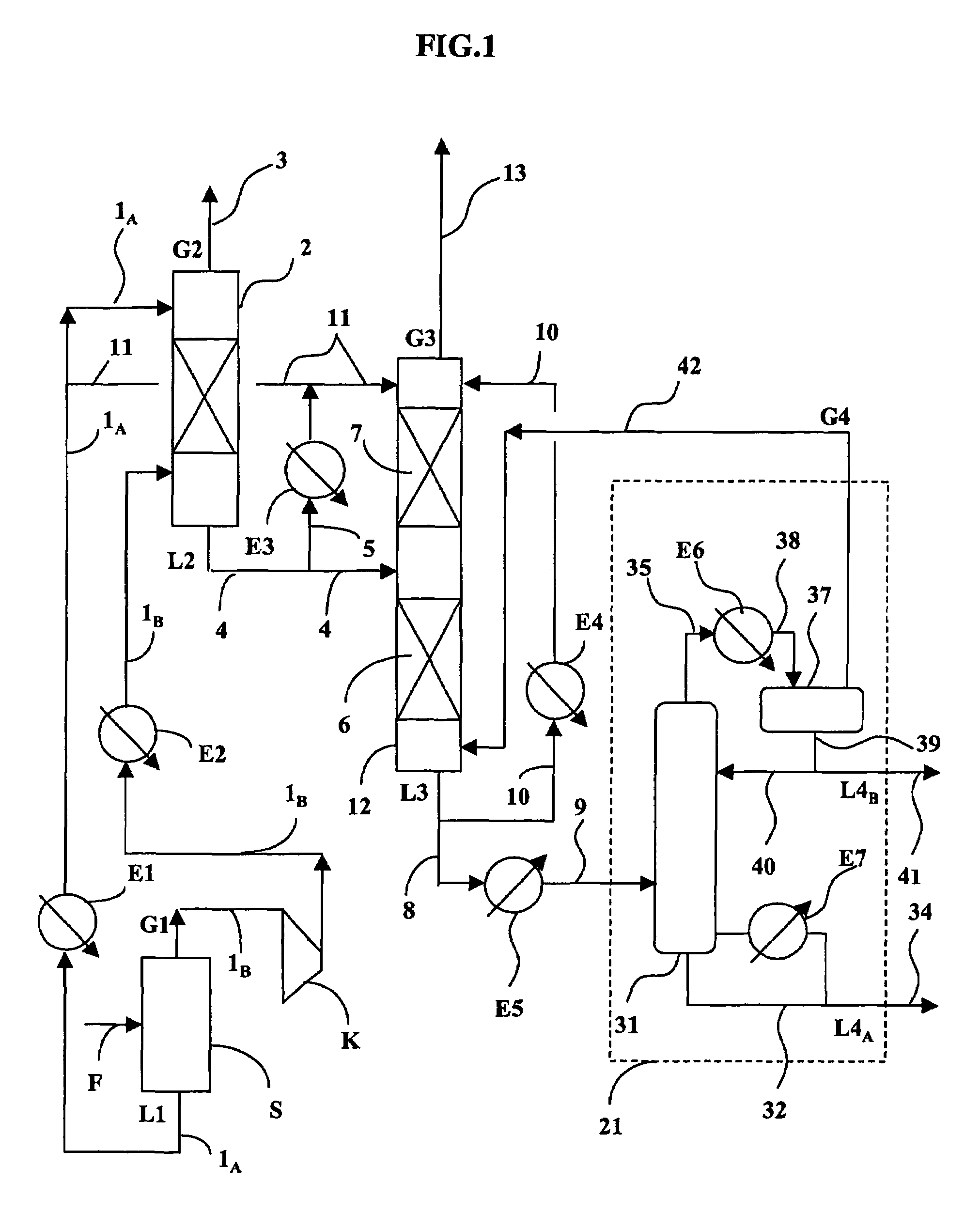
[0059]A catalytic reforming effluent that exits under a pressure of 0.5 MPa is fed into an installation of the prior art according to a process that is not in accordance with that of the invention, for which the pieces of equipment differ from those of FIG. 1 in that pieces of equipment 2 and 12 are not columns but simple gas / liquid separator tanks that are fed at an ambient temperature of 31° C. Lines 1A and 1B are then merged at the inlet of the separator tank that replaces column 2. In an analogous way, column 12 is replaced by a simple separator tank; lines 5, 11 and 10 are eliminated, and gas G4 is mixed in line 4 that is upstream from the separator tank with liquid L2, at 31° C., that is obtained from the first separator tank. The flows that enter into the separator tank are provided in Table 1:
[0060]
TABLE 1Kg / hInput (5)Liquid Output (8)Gas Output (13)H2291019C128322855C223822251131C33613355062iC41682167012NC42550253713C5+889998898316Total Kg / h9953899229309Press...
example 2
According to the Invention
[0061]The installation of Example 1 is used with the consistent modification to replace the (second) separator tank by an absorption column 12. This column comprises a single absorption zone 7 with 5 theoretical stages (whereby zone 6 that is shown in FIG. 1 is eliminated). A liquid AL2 that represents 5% by mass (or 5100 kg / h) of liquid flow L3 that exits from the column via pipe 8 is sampled via line 10, cooled to −5° C. in exchanger E4 and reinjected at the top of the column. The operating conditions are indicated in Table 2.
[0062]
TABLE 2Kg / hInput (5)Liquid Output (8)Gas Output (13)H228919C131225160C23403330794C34688465834iC4199019865NC4290128975C5+89268892614Total Kg / h102590102369221Pressure MPa1.61.61.5Temperature ° C.35340
[0063]The comparison of Tables 1 and 2 shows that the loss in LPG in the column top gas (line 13) drops from 87 kg / h to 44 kg / h by using the invention and is therefore essentially reduced by half.
PUM
| Property | Measurement | Unit |
|---|---|---|
| temperature | aaaaa | aaaaa |
| temperature | aaaaa | aaaaa |
| temperature | aaaaa | aaaaa |
Abstract
Description
Claims
Application Information