
Image forming system, image forming apparatus, and control method thereof

a technology of image forming and forming system, applied in the direction of digital output to print units, corona discharge, instruments, etc., can solve the problems of non-uniformity or a mounting position shift of a lens, registration errors, etc., and achieve the effect of suppressing processing load

Inactive Publication Date: 2008-11-18
CANON KK
View PDF11 Cites 8 Cited by
  • Summary
  • Abstract
  • Description
  • Claims
  • Application Information

AI Technical Summary

Benefits of technology

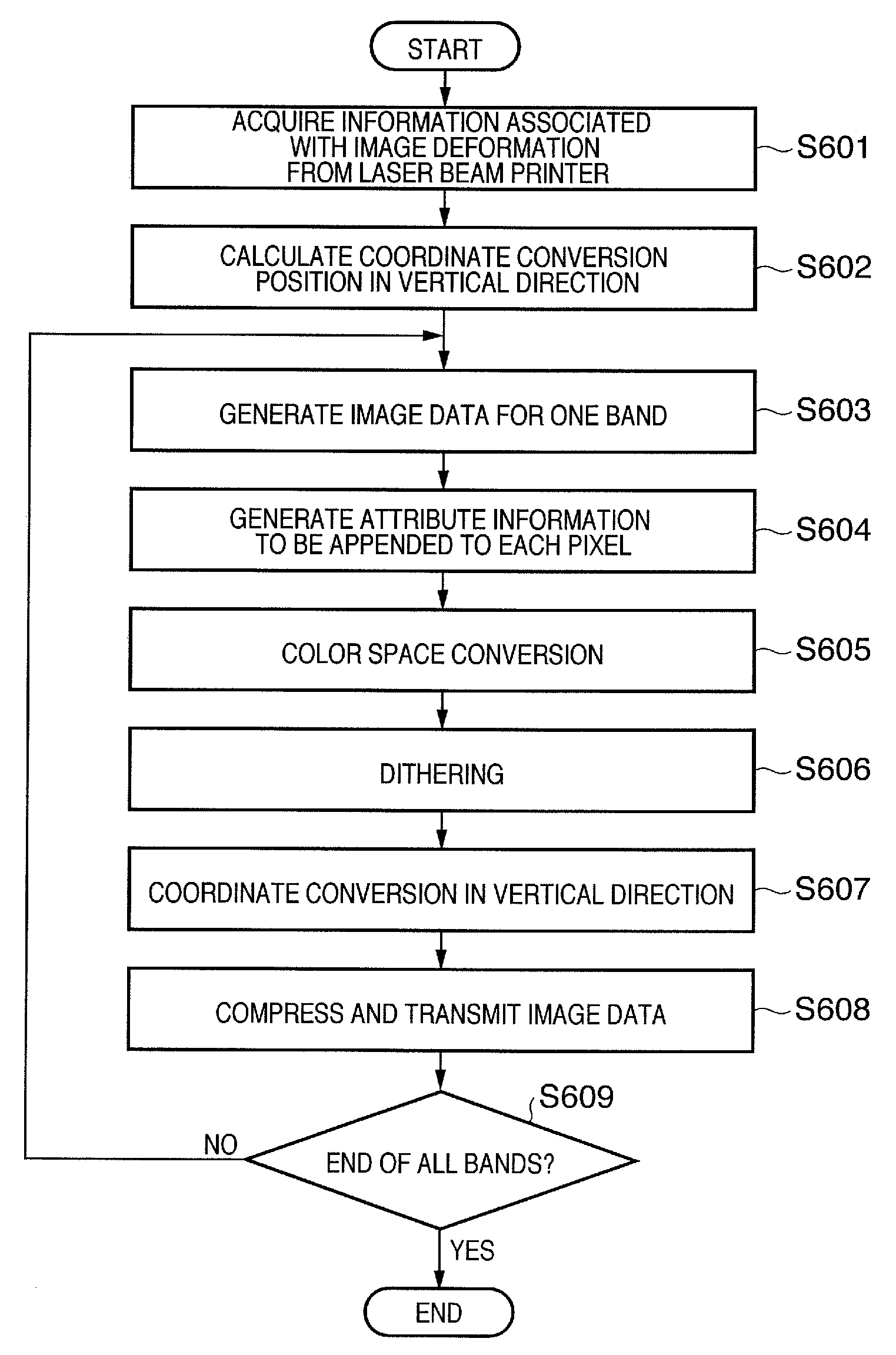
[0026]According to the present invention, an image forming apparatus which can suppress the processing load on the host computer side, and can apply correction to remove any deformation of an image output from an image forming apparatus is provided.

Problems solved by technology

For example, one such factor is non-uniformity or a mounting position shift of a lens used in an exposure scan device used to expose each photosensitive drum.
With these factors, a laser scan line that exposes each photosensitive drum (image carrier) deforms with respect to the photosensitive drum, and if such deformation varies for respective colors, registration errors occur.

Method used


Image

  • Image forming system, image forming apparatus, and control method thereof
  • Image forming system, image forming apparatus, and control method thereof
  • Image forming system, image forming apparatus, and control method thereof

Examples


first embodiment

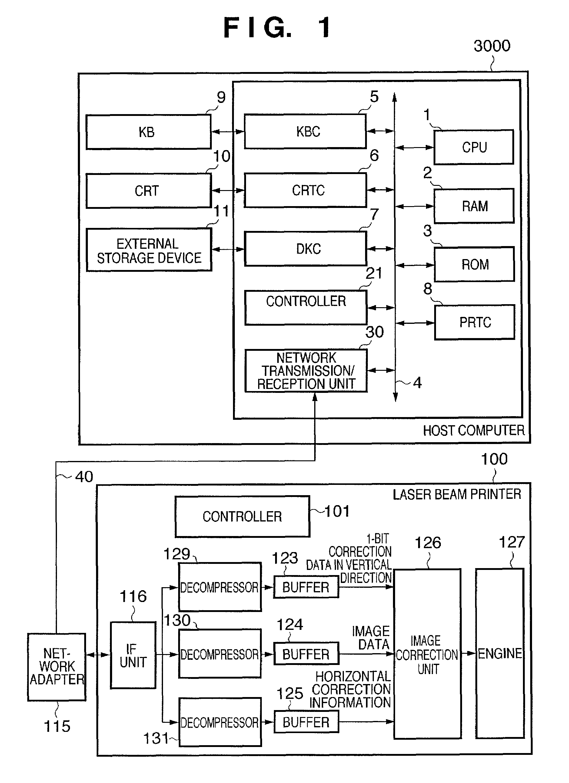
[0042]A printing system according to one embodiment of the present invention will be described below with reference to the accompanying drawings. Note that this embodiment uses a printing system in which a host computer and a printing apparatus are connected via a network. As the printing apparatus, a laser beam printer capable of monochrome printing is used.

[0043]FIG. 1 is a block diagram showing the arrangement of a printing system according to the first embodiment of the present invention. Referring to FIG. 1, reference numeral 3000 denotes a host computer, in which a CPU 1 executes programs which are stored in an external storage device 11 and are loaded into a RAM 2. The programs to be loaded into the RAM 2 include device drivers used to execute scan processing and print processing, an application program for executing processing of documents that include any combinations of graphics data, image data, text data, table data (including a spreadsheet), and the like together based ...

second embodiment

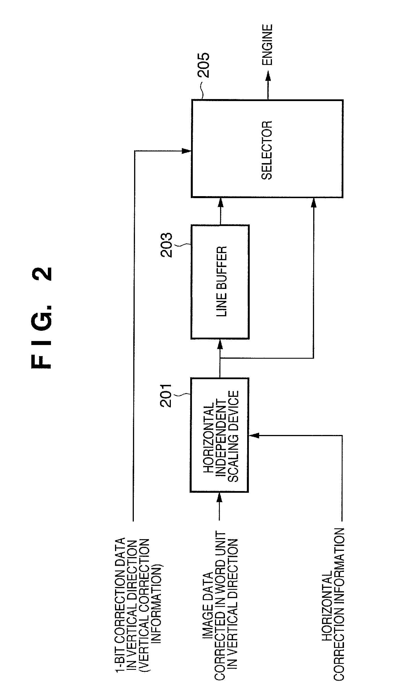
[0069]In the first embodiment, since the host computer executes correction processing in a word unit in the vertical direction, and the printer executes correction processing (complementary processing) in a pixel unit, the load associated with the correction processing in the host computer and printer is distributed. However, the method of the first embodiment often requires correction processing (interpolation processing) in less than one pixel for steps or the like which are generated in the corrected image upon correction in a pixel unit. Hence, in the second embodiment, the host computer executes correction in a pixel unit in the vertical direction, and the printer executes correction processing (interpolation processing) in less than one pixel, thus distributing the load associated with the correction processing of the host computer and printer.

[0070]Note that the overall arrangement of the printing system including the host computer 3000 and laser beam printer 100 is the same ...


PUM


Abstract

Correction for eliminating deformations of an image to be output from an image apparatus is executed while suppressing the processing load on the host computer side. A host computer acquires deformation information used to designate read addresses according to deformations of a scan line from a laser beam printer. A CPU (1) of the laser beam printer generates read addresses according to the deformation information to read out image data from a RAM, and transmits the readout image data to the laser beam printer. The laser beam printer (0) forms an image based on the image data received from the host computer (3000).

Description

TECHNICAL FIELD[0001]The present invention relates to an image forming system, image forming apparatus, and control method thereof.BACKGROUND ART[0002]In recent years, in order to increase the image forming speed in a color image forming apparatus of an electrophotography system, color image forming apparatuses of a tandem system, each of which comprises developers and photosensitive drums in a number as large as the number of color materials, and transfers images of different colors on an image conveyor belt or print medium, are increasing. In such a color image forming apparatus of a tandem system, there are a plurality of factors that cause registration errors (color discrepancy), and various strategies against respective factors have been proposed.[0003]For example, one such factor is non-uniformity or a mounting position shift of a lens used in an exposure scan device used to expose each photosensitive drum. Another factor is an assembly position shift of the exposure scan devi...

Claims


Application Information

Patent Timeline
Patent Type & Authority Patents(United States)
IPC IPC(8): H04N1/46
CPCH04N1/4072H04N1/506G03G15/5087G03G15/04072G03G15/043B41J2/44B41J5/30G02B26/12G03G15/01
Inventor KAMBEGAWA, MINORUMORITA, SEIJIRO
Owner CANON KK
Learn More