Perforate projection screen with inconspicuous seams

a projection screen and inconspicuous seam technology, applied in the field of perforated projection screens, can solve the problems of destroying the desired continuity of the projection screen, unable to eliminate the shadow of the edge sufficiently, and still visible seams

Inactive Publication Date: 2008-11-18
ASTRO TEC MFG
View PDF11 Cites 7 Cited by
  • Summary
  • Abstract
  • Description
  • Claims
  • Application Information

AI Technical Summary

Benefits of technology

[0008]It is a primary object of this invention to provide a perforate projection screen utilizing a simple and inexpensive solution to the problem of non-uniform reflectivity in lap joint areas of the projection screen and in areas of the screen where frame members or other objects are located in contact with or in close proximity to the back side of the screen.
[0012]This invention is a perforate projection screen with substantially uniform reflectivity throughout its visible surface comprising at least one perforate panel having a light reflective surface on one side thereof and a plurality of rows of holes therethrough located substantially throughout the entire reflective surface of each such panel, a plurality of edge portions extending around the panel, each such panel adapted to be mounted a spaced distance from a substantially non-reflective surface, thereby creating a substantially uniformly dark non-reflective chamber behind the panel, each panel being mounted with at least one of its edge portions overlapping an edge portion of the next adjacent panel to form a seam; and a dark material covering the surfaces of any objects which are in sufficiently close proximity to the back of the panel to be visible through the holes in the panel without such covering, said dark material having a textured surface comprised of a plurality of dark fibers extending vertically from the surface thereof to reduce the surface reflectivity of all such objects so that they are not visible through the holes in the panels, at least part of the overlapped edge portions of each overlapped panel being crimped to form an offset strip which is recessed from the rest of the light reflective surface of the panel a sufficient distance so that when each overlapped overlapping panel is placed in overlapping position with the offset overlapped strip, the light reflective surface of the overlapped panel and the overlapping panel are flush with each other and the edge of the overlapping panel is hidden by its position in the recess of the offset overlapped strip.

Problems solved by technology

One of the problems encountered when using a perforate screen is that when lap joints are used to connect adjacent perforate panels of the screen, the holes in overlapping edges of the adjacent panels are not always in alignment with each other and the surface of the overlapped panel sometimes shows through the holes in the overlapping panel edge thereby creating a strip of greater reflectivity than the rest of the surfaces of the panels where the holes are not blocked by the surface of an overlapped panel, or by a supporting frame member or some other object in close proximity to the back of the panel.
These strips or areas show up as light strips or other shapes on the screen and thereby break the desired continuity of the screen and distract from the images being projected on the screen.
In addition to the problem of non-uniform reflectivity described above, when the perforate patents are overlapped at interconnecting seams, a shadow is formed at the edge of the overlapped to panel which is visible when viewing the screen.
Attempts have been made to solve this problem by beveling the edge of the overlapping panel to reduce the shadow appearing on the edge as may be seen in U.S. Pat. No. 3,992,841 issued to R Ward Jr and my prior U.S. Pat. No. 5,011,263, however, it has been found that beveling the edge does not sufficiently eliminate the shadow and the seam can still be seen by viewers of the screen.

Method used


Image

  • Perforate projection screen with inconspicuous seams
  • Perforate projection screen with inconspicuous seams
  • Perforate projection screen with inconspicuous seams

Examples


Embodiment Construction

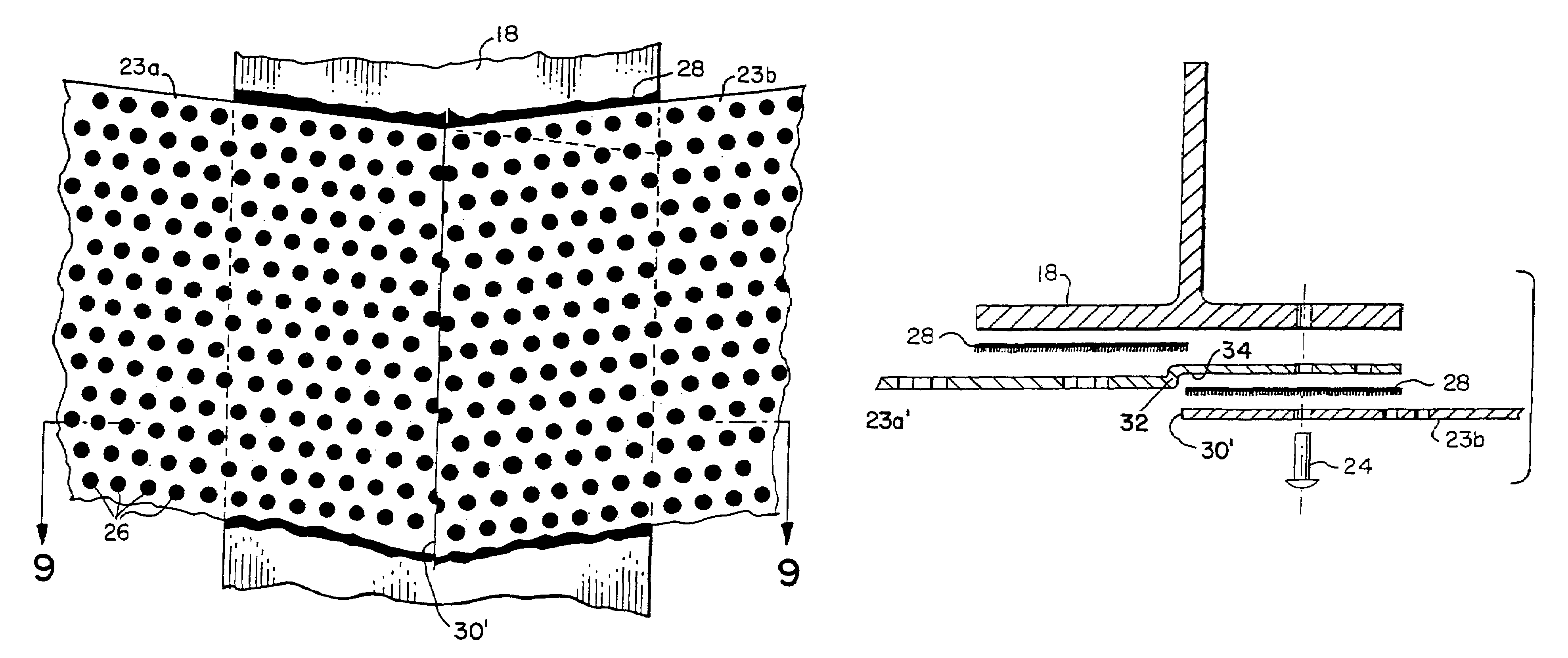
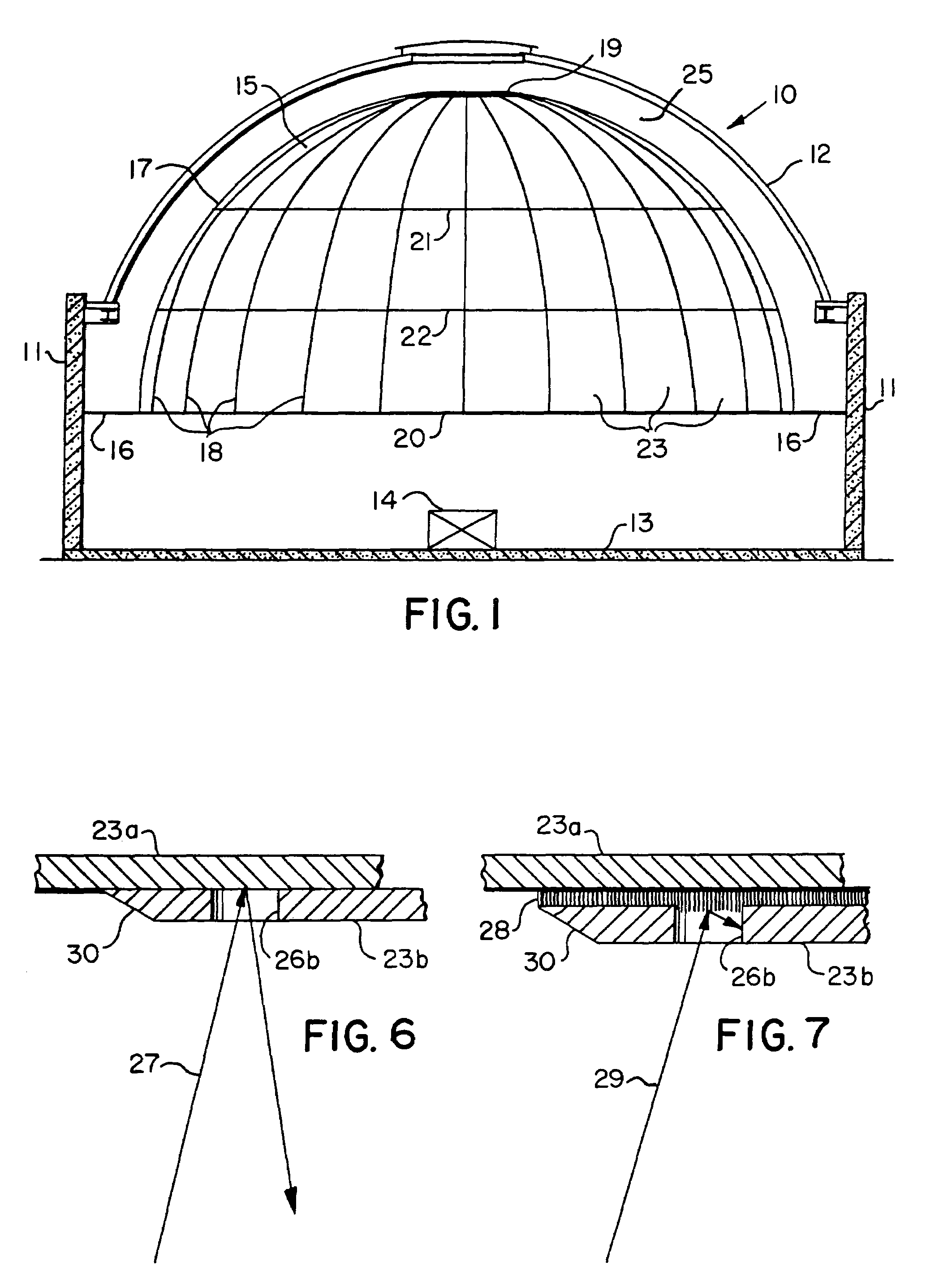
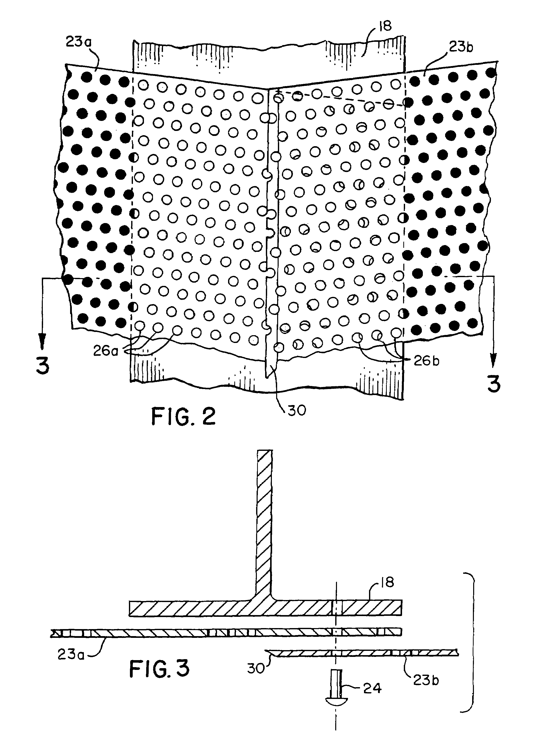
[0024]Referring now to the drawings and in particular to FIG. 1, a planetarium indicated generally by the numeral 10 has vertical side walls 11 with a spherical shaped exterior dome 12 mounted thereon. A floor 13 extends between the side walls 11 and has a projection area 14 near the center thereof. A perforate screen 15 in the shape of a geodesic dome or hemisphere is attached to the side walls 11 by suitable connecting frame members 16. The screen 15 is supported by a hemispherical frame assembly 17 consisting of a plurality of arcuate frame members 18 extending radially outwardly and downwardly from a top ring 19 to a bottom ring 20. A pair of intermediate rings 21 and 22 are attached, by bolts and brackets or any other suitable means, to each of the frame members 18 between the top ring 19 and bottom ring 20. The rings 19, 2021 and 22 all lie in parallel horizontal planes.

[0025]The frame members 18 and the rings 19 through 22 may be made of beams or tubing of aluminum or other s...


PUM


Abstract

A perforate projection screen for movies, planetariums and the like having inconspicuous seams and uniform reflectivity throughout its visible surface. The screen is made from a plurality of perforate panels and is mounted, when in use, with a dark non-reflective chamber behind the screen. Any overlapped areas of the panels and any frame members or other objects, in close proximity to the back of the panels are covered with a black velour type material to prevent light reflection from panel holes where objects are in close proximity to the back of the panel. The edges of adjacent panels overlap to form seams with the overlapped edges of the panels being crimped to form recesses to receive the overlapping edge strip of an adjacent panel, thereby hiding the overlapping panel edge to reduce shadow lines and make the panel edges inconspicuous to viewers.

Description

FIELD OF THE INVENTION[0001]This invention relates to a perforate projection screen having inconspicuous seams and substantially uniform reflectivity throughout its visible surface which may be used in applications such as a motion picture screen or a planetarium.BACKGROUND OF THE INVENTION[0002]The use of perforate projection screens is well known in the prior art as shown and described in U.S. Pat. No. 2,366,761 issued to R O Walker, U.S. Pat. No. 3,992,841 issued to R Ward, Jr and U.S. Pat. No. 4,750,807 issued to G Chamayou dit Felix.[0003]Perforate screens are particularly useful as spherical or geodesic dome shaped screens used in planetariums to permit the flow of heating and cooling air through the screen to the inside of the domed screen from the space between the screen and the exterior dome of the planetarium thereby assuring the proper ventilation and temperature is maintained inside the domed screen and the viewing area of the planetarium.[0004]One of the problems encou...

Claims


Application Information

Patent Timeline
Patent Type & Authority Patents(United States)
IPC IPC(8): G03B21/56E04B7/08G03B21/60
CPCG03B21/56
Inventor HOPPER, CLAYTON LMCGREW, KEVIN P
Owner ASTRO TEC MFG
Why Eureka
Try Eureka