Eureka AIR delivers breakthrough ideas for toughest innovation challenges, trusted by R&D personnel around the world.

Method and apparatus for longitudinal balance calibration

Inactive Publication Date: 2008-11-18
MICROSEMI SEMICON U S
View PDF8 Cites 8 Cited by
  • Summary
  • Abstract
  • Description
  • Claims
  • Application Information

AI Technical Summary

Benefits of technology

[0016]In one aspect of the present invention, a method is provided for performing longitudinal balance calibration. A differential signal is provided. A calibration of a gain of at least a portion of the differential signal to affect the longitudinal balance associated with the differential signal. Performing the calibration includes: receiving a first portion of the differential signal and determining a gain associated with the first portion; receiving a second portion of the differential signal and determining a gain associated with the second portion; determining a difference between the respective gains of the first and second portions to determine whether the difference is outside a predetermined range of tolerance; and modifying at least of the gain of the first portion and the gain of the second portion based upon a determination that the difference is difference is outside the predetermined range of tolerance.
[0017]In another aspect of the present invention, an apparatus is provided for performing longitudinal balance calibration. The apparatus of the present invention includes a first amplifier adapted to buffer a first portion of a differential signal and a second amplifier to buffer a second portion of the differential signal to generate a differential output signal. The apparatus also includes a calibration unit adapted to determine a difference between the gain of the first portion of the differential output signal

Problems solved by technology

POTS was designed primarily for voice communication, and thus provides an inadequate data transmission rate for many modern applications.
Many times, feedback configurations in the amplifiers that process the transmission signals cause noise and power problems.
Many of today's amplifier circuits may call for electronic components that have high bandwidth, which may increase consumption of power.
Many times, power consumption in the line card can become undesirably high.
Amplifier circuits that are used to condition communication signals often consume large amounts of power.
Excessive power use can compromise the effectiveness of line cards, particularly for remote line cards, which rely upon portable power supplies.
Excessive power consumption can also require additional resources to counteract the effects of high power consumption, such as additional cooling systems to keep line card circuitry in operating condition.
Excessive power consumption can also require additional circuits to furnish the required amounts of power needed for efficient operation of line cards.
Excessive power consumption can cause appreciable inefficiencies in the operation of line cards and the communication system as a whole.
Among the problems associated with the current implementations, include the fact that a larger signal is fed back into the circuit described above.
The problem with such an implementation is that larger signals may generally carry larger amounts of noise.
Therefore, feeding back larger signals amounts to feeding back larger amounts of noise into the circuit, which may cause performance problems in the amplifier circuit.
Additionally, feeding back the output voltage signal may require amplifiers that have relatively large bandwidth capabilities.
Utilizing amplifiers with larger bandwidth capabilities generally increases power consumption.
The circuits that use these types of configurations may experience an excessive amount of longitudinal signals, such as longitudinal currents.
Longitudinal signals may enter one or more amplification stages within a circuit and cause excessive noise.
Utilizing the current methodologies, the performance of a signal conditioning circuit may be compromised.
Often, longitudinal imbalance may occur in circuits that employ multiple signals or differential-type amplifiers.
The forward paths of the tip and ring signals may contain longitudinal imbalance that may cause signal degradation or errors in telecommunications.
The common mode error that exists on the differential-type circuits can cause significant errors in telecommunications.

Method used


Image

  • Method and apparatus for longitudinal balance calibration
  • Method and apparatus for longitudinal balance calibration
  • Method and apparatus for longitudinal balance calibration

Examples


Embodiment Construction

[0028]Illustrative embodiments of the invention are described below. In the interest of clarity, not all features of an actual implementation are described in this specification. It will of course be appreciated that in the development of any such actual embodiment, numerous implementation-specific decisions must be made to achieve the developers' specific goals, such as compliance with system-related and business-related constraints, which will vary from one implementation to another. Moreover, it will be appreciated that such a development effort might be complex and time-consuming, but would nevertheless be a routine undertaking for those of ordinary skill in the art having the benefit of this disclosure.

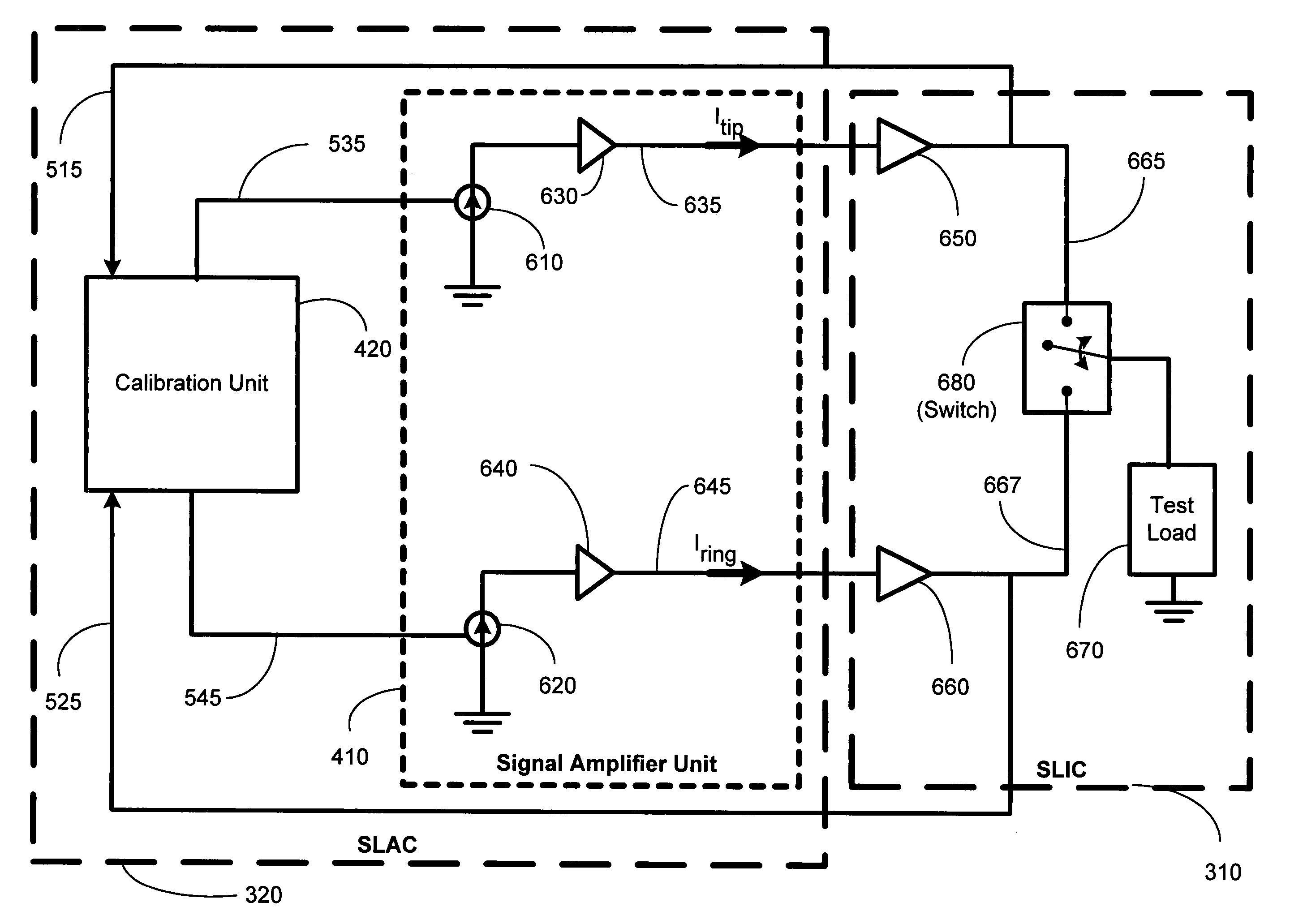
[0029]Embodiments of the present invention provide for promoting longitudinal balance in a differential-type circuit. Telecommunication circuits may comprise various differential signals, such as tip and ring signals. Common mode rejection ratios in the differential-type circuits...


PUM


Abstract

A method and apparatus is provided for performing longitudinal balance calibration. A differential signal is provided. A calibration of a gain of at least a portion of the differential signal to affect the longitudinal balance associated with the differential signal. Performing the calibration includes: receiving a first portion of the differential signal and determining a gain associated with the first portion; receiving a second portion of the differential signal and determining a gain associated with the second portion; determining a difference between the respective gains of the first and second portions to determine whether the difference is outside a predetermined range of tolerance; and modifying at least of the gain of the first portion and the gain of the second portion based upon a determination that the difference is outside the predetermined range of tolerance.

Description

BACKGROUND OF THE INVENTION[0001]1. Field of the Invention[0002]This invention relates generally to telecommunications, and, more particularly, to performing a calibration to improve longitudinal balance in a circuit.[0003]2. Description of the Related Art[0004]In communications systems, particularly telephony such as a Plain Old Telephone System (POTS), it is common practice to transmit signals between a subscriber station and a central switching office via a two-wire, bi-directional communication channel. A line card generally connects the subscriber station to the central switching office. The functions of the line card include supplying talk battery, performing wake-up sequences of circuits to allow communications to take place, and the like. Voltage signals are processed and conditioned when being driven onto telecommunication lines.[0005]POTS was designed primarily for voice communication, and thus provides an inadequate data transmission rate for many modern applications. To ...

Claims


Application Information

Patent Timeline
IPC IPC(8): H04M1/00
CPCH04M3/007H04M11/062
Inventor BASS, ERIC
Owner MICROSEMI SEMICON U S
Why Eureka
Eureka Blog
Learn More