Method and apparatus for adjustably mounting a speaker

a technology for mounting and adjusting a speaker, which is applied in the direction of washstands, scaffold accessories, lightening support devices, etc., can solve the problems of high manufacturing and implementation costs, unfavorable design, and general inconvenience of users, and achieves convenient and accessible mounting and adjustment, stable and secure mounting of the body, and simple design

Inactive Publication Date: 2008-11-25
RGB SYST INC
View PDF13 Cites 36 Cited by
  • Summary
  • Abstract
  • Description
  • Claims
  • Application Information

AI Technical Summary

Benefits of technology

[0017]The mount of the invention has numerous advantages and features, including a simple design, a convenient and accessible mounting and adjustment configuration, and configuration ensuring stable and secure mounting of the body to a structure in desired position.

Problems solved by technology

Unfortunately, this mounting only permits the speaker to be moved in one plane or direction—generally up or down about a horizontal axis through swivel pins connecting the mount to the speaker.
These mounts generally have a number of undesirable drawbacks, however.
On the other hand, this mount has a very complex design.
This design, including location of a variety of moving parts within the speaker enclosure itself, renders the design costly to manufacture and implement, and occupies a great deal of space within the speaker, which compromises the function of the speaker.
The design of this mount limits its use with only specially designed speakers and no others.
Another issue is that the adjusting mechanism is dependent solely upon pressure applied by a clamp to a ball.
In this configuration, the clamping force is applied through the speaker body itself, and the clamping force may be limited.
Moreover, this clamp is the only means by which the speaker is connected to a wall, so that if the ball loosens from the clamp, the speaker can fall from the mount and be damaged or destroyed.

Method used


Image

  • Method and apparatus for adjustably mounting a speaker
  • Method and apparatus for adjustably mounting a speaker
  • Method and apparatus for adjustably mounting a speaker

Examples


Embodiment Construction

[0027]The invention comprises a method and apparatus for adjustably mounting body, such as a speaker, to a support structure. In the following description, numerous specific details are set forth in order to provide a more thorough description of the present invention. It will be apparent, however, to one skilled in the art, that the present invention may be practiced without these specific details. In other instances, well-known features have not been described in detail so as not to obscure the invention.

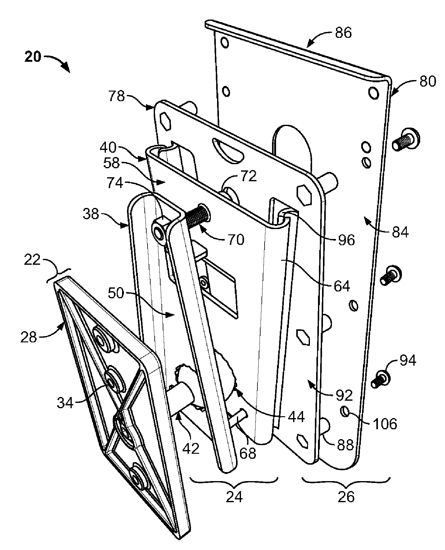
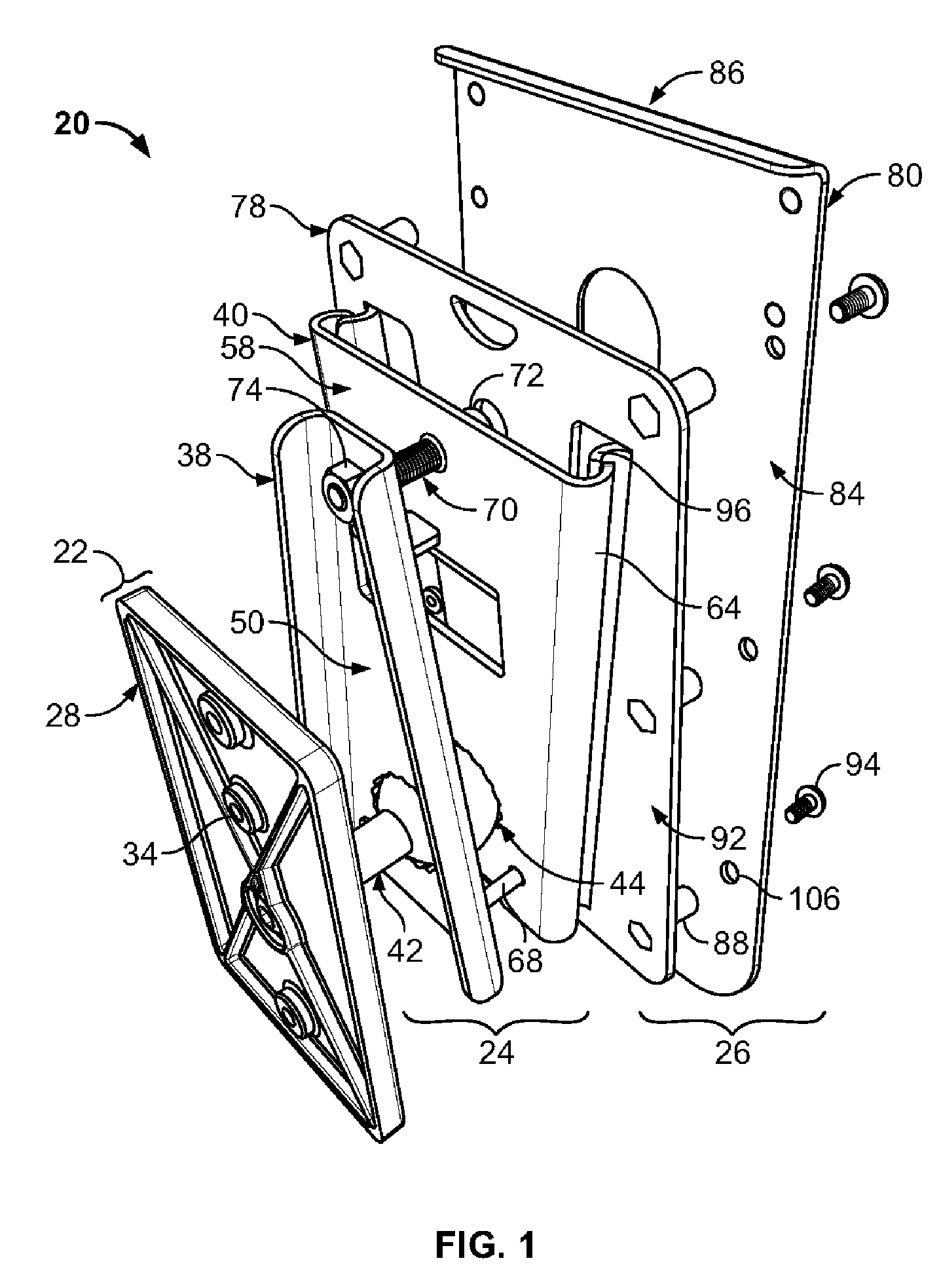
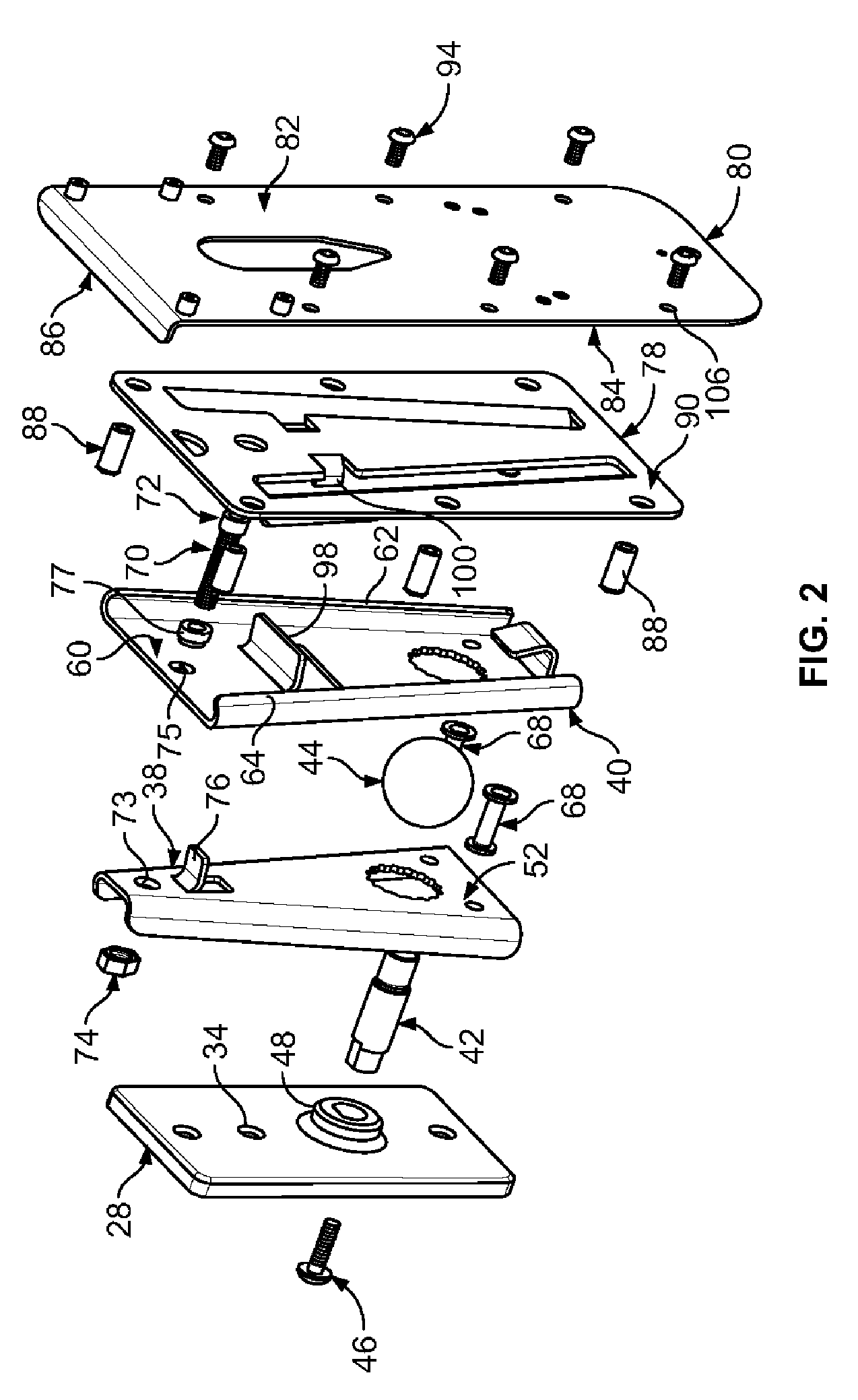
[0028]In general, the invention is an adjustable mount. The mount is configured to connect or support a body from a support structure such as a wall or post. The mount is configured to permit the supported or connected body to be positioned in a variety of orientations.

[0029]The mount has particular applicability to supporting a speaker, and as such the mount is referred to herein as a speaker mount, though it will be understood that the mount and method have other applicability a...


PUM


Abstract

A speaker mount includes a support structure attachment, an adjustable mount connected to the structure attachment and including a first connector, and a speaker attachment including a second connector. The first and second connectors may selectively be connected or disconnected, permitting a speaker to be connected to and disconnected from the remainder of the mount. The first connector is mounted to a ball. A lock plate is mounted at an opposing side of the ball from the first connector. A fastener controls the distance between the first connector and the lock plate. In one position, the fastener draws the lock plate and first connector towards one another, fixing the lock plate in a position on the ball, and in another position allows the first connector to be moved relative to the ball. The mount permits orientation of a speaker in a variety of positions relative to a support structure.

Description

FIELD OF THE INVENTION[0001]The present invention relates to adjustable mounts for bodies such as loudspeakers.BACKGROUND OF THE INVENTION[0002]Loudspeakers or “speakers” are used in a variety of settings and locations. Older speaker configurations were commonly “floor” speakers which were configured to set directly upon the floor. A variety of newer speaker designs are smaller and lighter and suitable for mounting to a wall, ceiling or other elevated support surface.[0003]It is desirable to orient speakers in particular directions, such as to optimize sound projection. In the case of floor mounted speakers, the speakers can easily be turned to change the direction they project sound. It is similarly desirable to permit the orientation of a wall or similarly located or mounted speaker to be changed.[0004]One common type of wall speaker mount is a “U” type bracket which mounts to the wall and connects to either side of a speaker. This bracket securely attaches the speaker to the wall...

Claims


Application Information

Patent Timeline
Patent Type & Authority Patents(United States)
IPC IPC(8): A47F5/00
CPCF16M11/14F16M13/02H04R1/026Y10T403/32631Y10T403/32196F16M2200/022
Inventor PINCEK, DAVIDEDWARDS, ANDREW C.STEWART, JR., WILLIAM CAMERONLU, XIAOZHENGCOE, STANLEY S.
Owner RGB SYST INC
Why Eureka
Try Eureka