Snap-on coaxial plug

a coaxial plug and socket technology, applied in the direction of coupling devices, two-part coupling devices, electrical equipment, etc., can solve the problems of plug damage, typical use of a somewhat unwieldy torque wrench,

Inactive Publication Date: 2008-11-25
TE CONNECTIVITY CORP
View PDF11 Cites 142 Cited by
  • Summary
  • Abstract
  • Description
  • Claims
  • Application Information

AI Technical Summary

Benefits of technology

[0006]In accordance with another aspect of the present invention, a plug component for use with connector systems having a plug component and a threaded jack component is provided. This plug component includes a first electrical contact; a second electrical contact positioned around the first electrical contact, wherein the second electrical contact further includes a plurality of outwardly-biased protrusions; a body positioned around the second electrical contact, wherein the body is adapted to receive the outwardly-biased protrusions formed on the second electrical contact and form a ground plane therewith; at least one biasing member positioned around the body, wherein the biasing member provides linear force sufficient to urge the second electrical contact against a jack component for maintaining a ground plane therewith; and a locking device positioned around the biasing member and the body, wherein the locking device is adapted to mechanically engage the threaded area on the jack component for attaching the plug component to the jack component.
[0007]In yet another aspect of this invention, a plug component for use with coaxial connector systems having plug components and threaded jack components is provided. This plug component includes a first electrical contact; a second electrical contact positioned around the first electrical contact, wherein the second electrical contact further includes a plurality of outwardly-biased protrusions; a body positioned around the second electrical contact, wherein the body is adapted to receive the outwardly-biased protrusions formed on the second electrical contact and form a ground plane therewith; at least one biasing member positioned around the body, wherein the biasing member provides axial linear force sufficient to urge the second electrical contact against a jack component for maintaining a ground plane therewith; and a locking device positioned around the biasing member and the body. The locking device further includes a substantially cylindrical member having a plurality of flared grasping arms formed at one end thereof; and a moveable collar for engaging the plurality of grasping arms and applying radial compressive force thereto for securely attaching the plug component to the threaded jack component.

Problems solved by technology

Turning the collar typically involves the use of a somewhat unwieldy torque wrench.
Because the use of the torque wrench is inconvenient, and may damage the plug if the wrench is improperly used, there is an ongoing need for an N connector system that does not require the use of a wrench.

Method used


Image

  • Snap-on coaxial plug
  • Snap-on coaxial plug
  • Snap-on coaxial plug

Examples


Embodiment Construction

[0021]Exemplary embodiments of the present invention are now described with reference to the Figures. Reference numerals are used throughout the detailed description to refer to the various elements and structures. In other instances, well-known structures and devices are shown in block diagram form for purposes of simplifying the description. Although the following detailed description contains many specifics for the purposes of illustration, a person of ordinary skill in the art will appreciate that many variations and alterations to the following details are within the scope of the invention. Accordingly, the following embodiments of the invention are set forth without any loss of generality to, and without imposing limitations upon, the claimed invention.

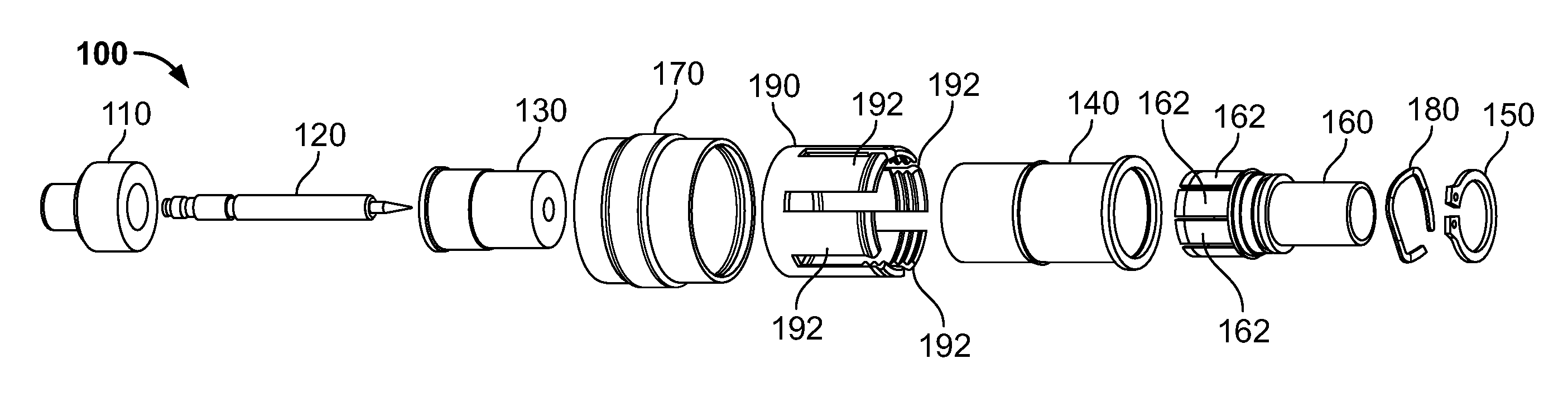
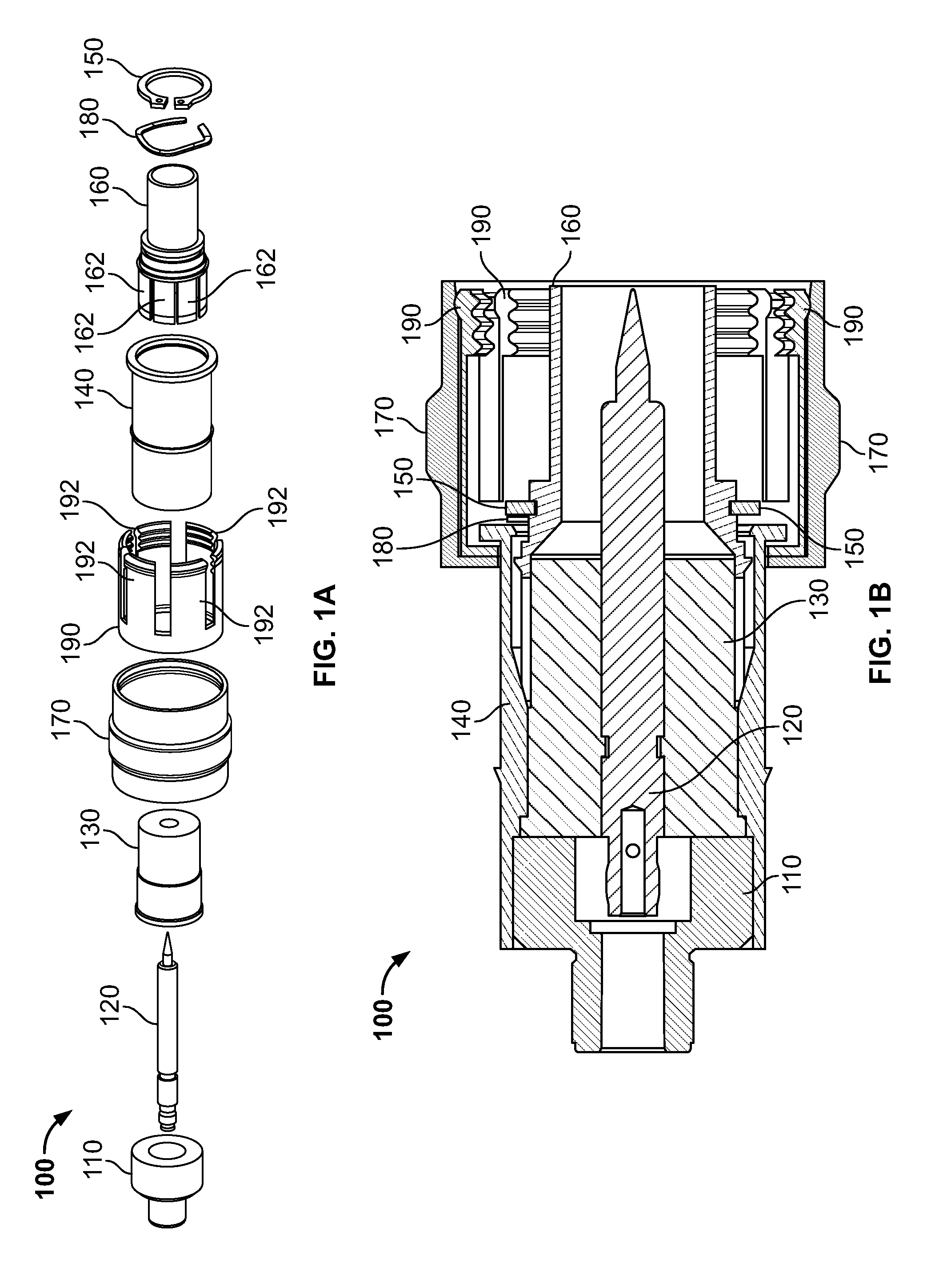
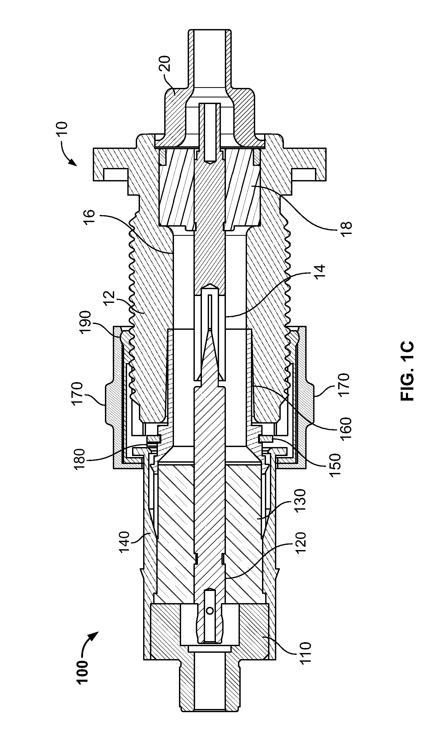
[0022]The present invention relates to a manual, single motion, snap-on plug component for use with a connector system. As previously indicated, a first general embodiment of this invention provides a coaxial connector system; a...


PUM


Abstract

A plug component for use with coaxial connector systems having a plug component and a threaded jack component is provided. This plug component includes a first electrical contact; a second electrical contact positioned around the first electrical contact, wherein the second electrical contact further includes a plurality of outwardly-biased protrusions; a body positioned around the second electrical contact, wherein the body is adapted to receive the outwardly-biased protrusions formed on the second electrical contact and form a ground plane therewith; at least one biasing member positioned around the body, wherein the biasing member provides linear force sufficient to urge the second electrical contact against a jack component for maintaining a ground plane therewith; and a locking device positioned around the biasing member and the body, wherein the locking device is adapted to mechanically engage the threaded area on the jack component for attaching the plug component to the jack component.

Description

BACKGROUND OF THE INVENTION[0001]The described invention relates in general to connector systems for use with electronic devices, and more specifically to an improved plug for use with connector systems of the type commonly used to join cables together.[0002]The Type N connector is a threaded connector used to join coaxial cables to one another. This connector was originally developed to provide a durable, weatherproof, medium-size radio frequency (RF) connector having consistent performance through 11 GHz and was one of the first connectors capable of carrying microwave-frequency signals. Currently, there are two basic families of Type N connectors: (i) the standard N (coaxial cable); and (ii) the corrugated N (helical and annular cable). The primary applications for these connectors are the termination of medium to miniature size coaxial cable, including RG-8, RG-58, RG-141, and RG-225. The N connector follows the MIL-C-39012 standard, defined by the US military, and comes in 50 a...

Claims


Application Information

Patent Timeline
Patent Type & Authority Patents(United States)
IPC IPC(8): H01R9/05
CPCH01R13/506H01R24/40H01R9/0527H01R2103/00
Inventor SYKES, MICHAEL TIMOTHY
Owner TE CONNECTIVITY CORP
Why Eureka
Try Eureka