Tether

a technology of tether and tether body, applied in the field of tether, can solve the problems of reducing the elastic resistance of the tether, the transmission of the entire force of deceleration to the second end of the conventional tether over a correspondingly short amount of time, and the range of responses

Inactive Publication Date: 2008-12-02
CASTLE MOUNTAIN ENTERPRISES
View PDF7 Cites 56 Cited by
  • Summary
  • Abstract
  • Description
  • Claims
  • Application Information

AI Technical Summary

Problems solved by technology

Conventional tethers which utilize a conventional elastic member having substantially homogeneous stretch and recovery characteristics along the entire length have a limited range of responses to a load as it is applied to and removed from the conventional tether.
This can be problematic in the context in which a first end of the conventional tether is coupled to a falling object (or otherwise traveling object) and the second end of the conventional tether has a fixed or substantially fixed location.
As the conventional elastic member stretches in response to the load generated by the falling (or traveling) object, the rate at which the falling object decelerates may be too little or too great over a given distance.
At the first extreme where the conventional tether has little or no elastic characteristic the rate of deceleration can be very great resulting in transmission of the entire force of deceleration to the second end of the conventional tether over a correspondingly short amount of time.
In this case, upon recovery of the conventional elastic member toward the original unstretched length, the conventional elastic member can generate an undesired amount of travel in the attached object in the opposite direction in which it fell or traveled.
Because there are a limited number of elastic materials which can be utilized as conventional elastic members of conventional tethers it can be difficult to generate the proper elastic characteristics in a conventional tether for certain applications.

Method used


Image

  • Tether
  • Tether
  • Tether

Examples


Embodiment Construction

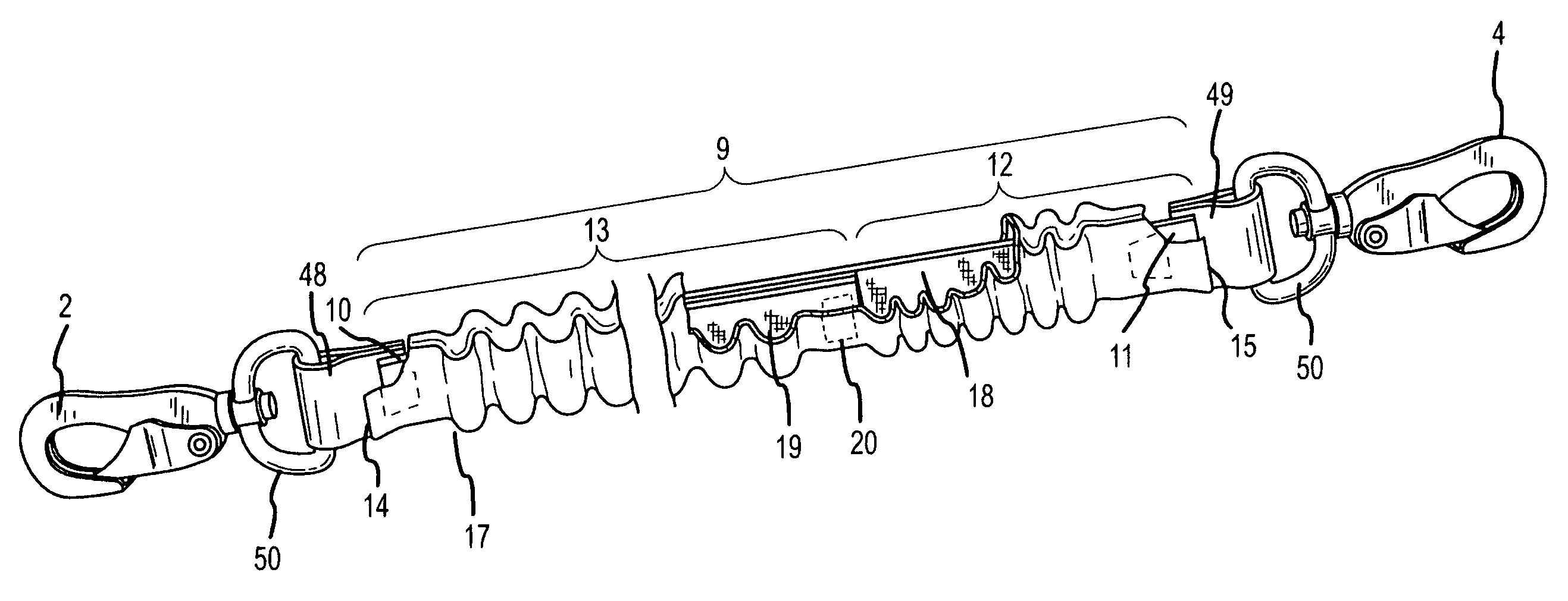
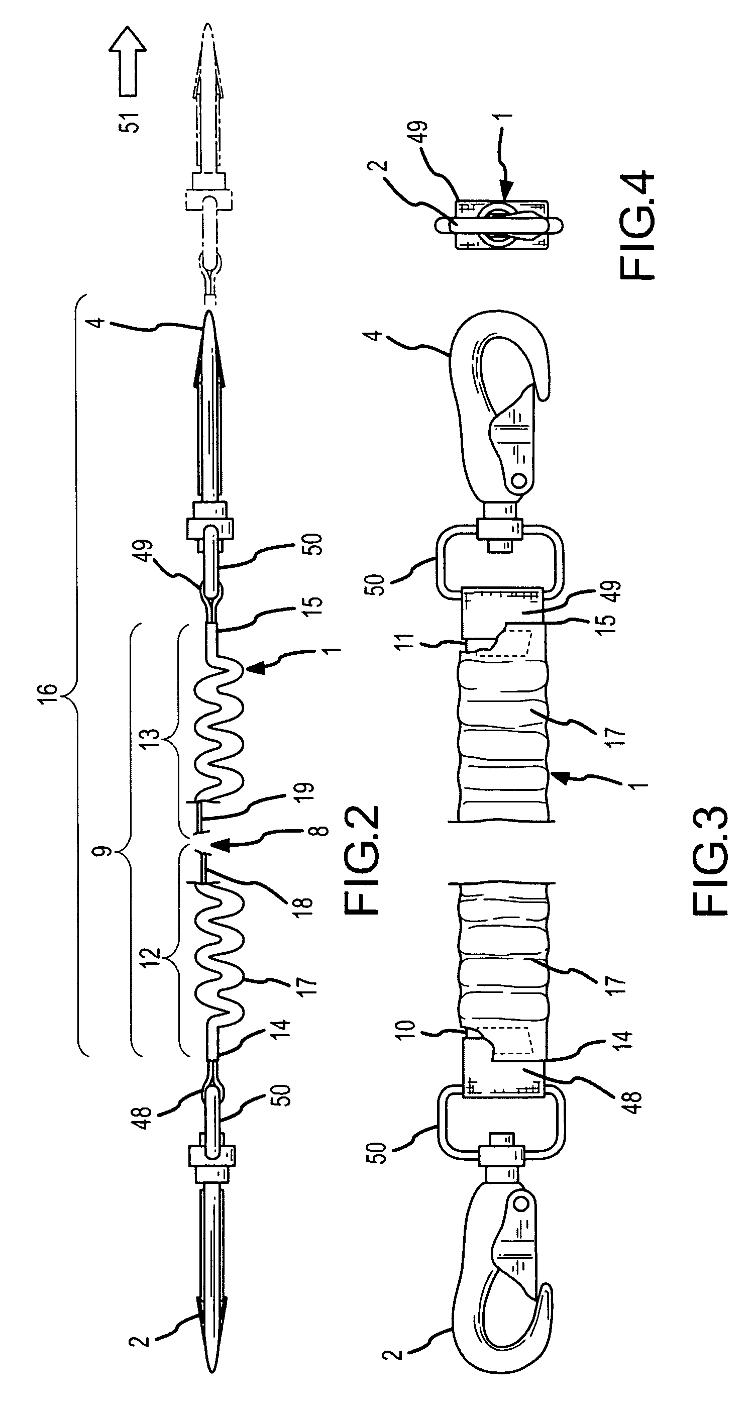
[0020]A tether having an elastic member which provides an unstretched length having a first part and a second part with the first part of the unstretched length having less elastic resistance than a second part of the unstretched length to alter characteristics of stretch and recovery toward the unstretched length under load.

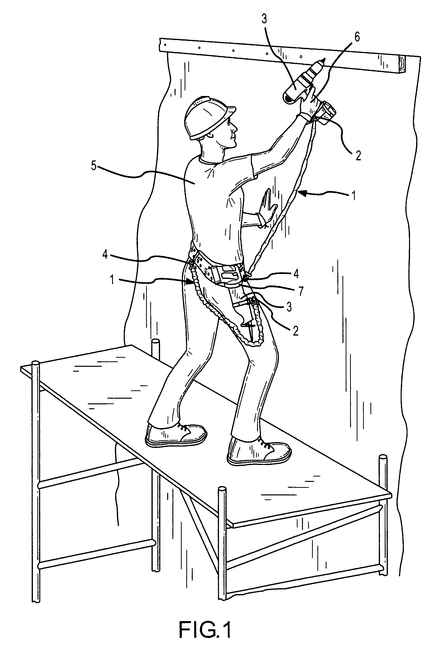
[0021]Now referring primarily to FIG. 1, a particular method of using the inventive tether (1) is shown. The inventive tether (1) can be connected by a first fastener (2) to a tool (3) (or other object) and connected by a second fastener (4) to a person (5)(or a part of a person, the person's clothing, tool belt, or to another object) to establish a limited range of travel for the tool (3)(or other object). As a non-limiting example, if the tool (3) falls from a person's hand (6) or becomes disengaged from a tool restraint (7), or is otherwise urged to travel or falls under the influence of gravity, the distance and travel path of the tool (3) can be limited by ...


PUM


Abstract

A tether having an elastic member which provides an unstretched length having a first part and a second part with the first part of the unstretched length having less elastic resistance than a second part of the unstretched length to alter characteristics of stretch and recovery toward the unstretched length under load and unloaded conditions.

Description

[0001]This United States Patent Application is a continuation-in-part of U.S. patent application Ser. No. 11 / 414,603, filed Apr. 28, 2006, and claims the benefit of U.S. Provisional Patent Application No. 60 / 738,479, filed Nov. 21, 2005, hereby incorporated by reference herein.I. BACKGROUND[0002]A tether having an elastic member which provides an unstretched length having a first part and a second part with the first part of the unstretched length having less elastic resistance than a second part of the unstretched length to alter characteristics of stretch and recovery toward the unstretched length under load.[0003]Conventional tethers, leashes, or other devices coupled between a pair of objects to limit the range of travel of a first of the pair of objects relative to the second of the pair of objects (hereinafter “conventional tether”) have either no elastic member or an elastic member having substantially homogeneous stretch and recovery characteristics along the entire length (...

Claims


Application Information

Patent Timeline
Patent Type & Authority Patents(United States)
IPC IPC(8): A45C13/30A45F3/14A45F5/00
CPCB25H3/006Y10T24/316Y10T24/314A45F5/00A45F5/021A45F2005/006A45F2005/008A45F2200/0575
Inventor MIKESELL, KENNETH W.BIBLE, MICHAEL J.
Owner CASTLE MOUNTAIN ENTERPRISES
Why Eureka
Try Eureka