
Control system for reducing internally generated frictional and inertial resistance to manual positioning of a surgical manipulator

a control system and manipulator technology, applied in the field of robotic surgical systems, can solve the problems that the internal generated frictional and inertial resistance to manual movement of the slave manipulator may be objectionable to the assistant, and achieve the effect of reducing the internal generated frictional and inertial resistan

Active Publication Date: 2007-06-21
INTUITIVE SURGICAL OPERATIONS INC
View PDF5 Cites 111 Cited by
  • Summary
  • Abstract
  • Description
  • Claims
  • Application Information

AI Technical Summary

Benefits of technology

[0011]Accordingly, an object of aspects of the present invention is a control system for reducing internally generated frictional and inertial resistance to manual positioning of the slave manipulator.
[0012]This and additional objects are accomplished by the various aspects of the present invention, wherein briefly stated, one aspect is a robotic surgical system comprising a slave manipulator and a controller. The slave manipulator has jointed structures for providing multiple degrees of freedom movement to a surgical instrument when the instrument is coupled to the slave manipulator, joints corresponding to the jointed structures, motors to drive movement of the joints, and sensors to measure movement of the joints. The controller is configured with at least one control system generating a signal by processing measurements received from a corresponding one of the sensors to drive a corresponding one of the motors so as to reduce internally generated frictional and inertial resistance when manually moving at least a portion of the slave manipulator in order to position and / or orientate the surgical instrument at a surgical site within a patient.
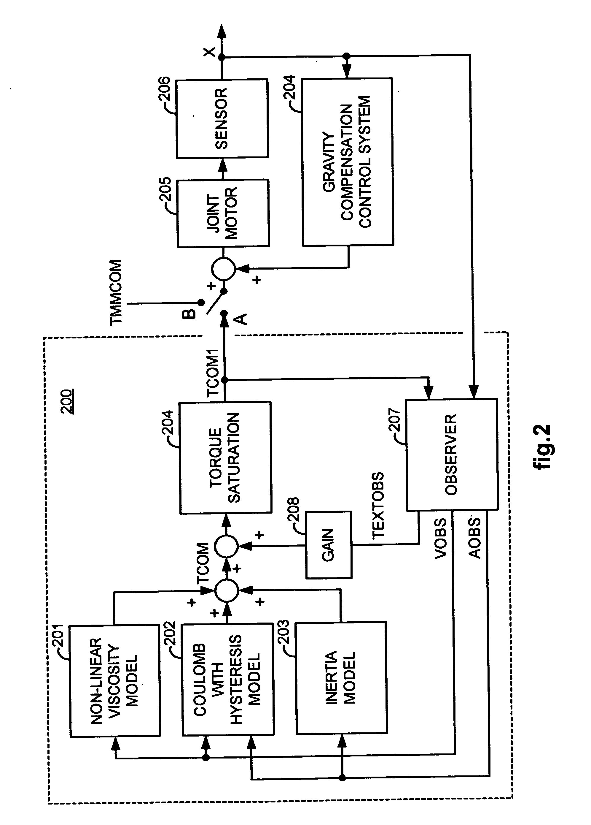
[0013]Another aspect is a method for reducing internally generated frictional and inertial resistance when manually moving a slave manipulator, comprising: receiving sampled displacement measurements corresponding to movement of a joint in the slave manipulator; generating a first signal to compensate for internally generated non-linear viscous friction when manually moving the slave manipulator; generating a second signal to compensate for internally generated Coulomb friction when manually moving the slave manipulator; generating a third signal to compensate for internally generated inertial resistance when manually moving the slave manipulator; generating a fourth signal by adding or combining at least the first, second, and third signals; and driving a motor corresponding to the joint using the fourth signal.
[0014]In still another aspect, a robotic surgical system includes a slave manipulator which is coupled to a surgical instrument. The slave manipulator is configured so as to have a plurality of joints, a plurality of motors driving the joints, and a plurality of sensors for detecting motion of the joints. Also in the robotic surgical system is a control system comprising: an observer coupled to one of the sensors and configured to estimate at least an angular or linear velocity and acceleration of the joint corresponding to the sensor; and a signal generator configured to generate a signal to drive the motor corresponding to the joint so as to reduce internally generated frictional and / or inertial resistance when manually moving at least a portion of the slave manipulator in order to position or orientate the surgical instrument.

Problems solved by technology

In the second part of the positioning procedure, however, internally generated frictional and inertial resistance against manual movement of the slave manipulator may be objectionable to the assistant, because a finer control of the instrument tip is required while it is moved inside the surgical cavity.

Method used


Image

  • Control system for reducing internally generated frictional and inertial resistance to manual positioning of a surgical manipulator
  • Control system for reducing internally generated frictional and inertial resistance to manual positioning of a surgical manipulator
  • Control system for reducing internally generated frictional and inertial resistance to manual positioning of a surgical manipulator

Examples


Embodiment Construction

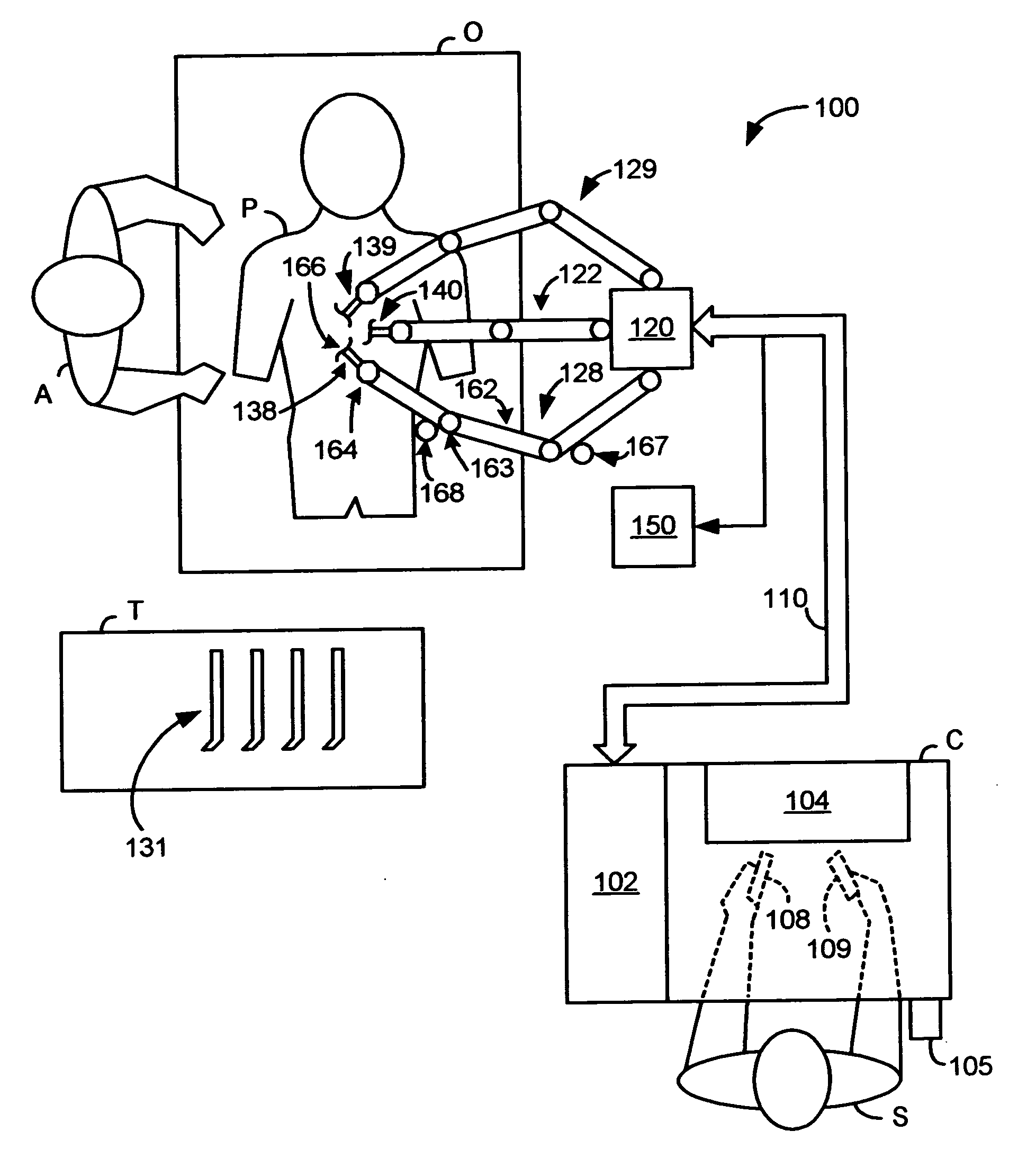
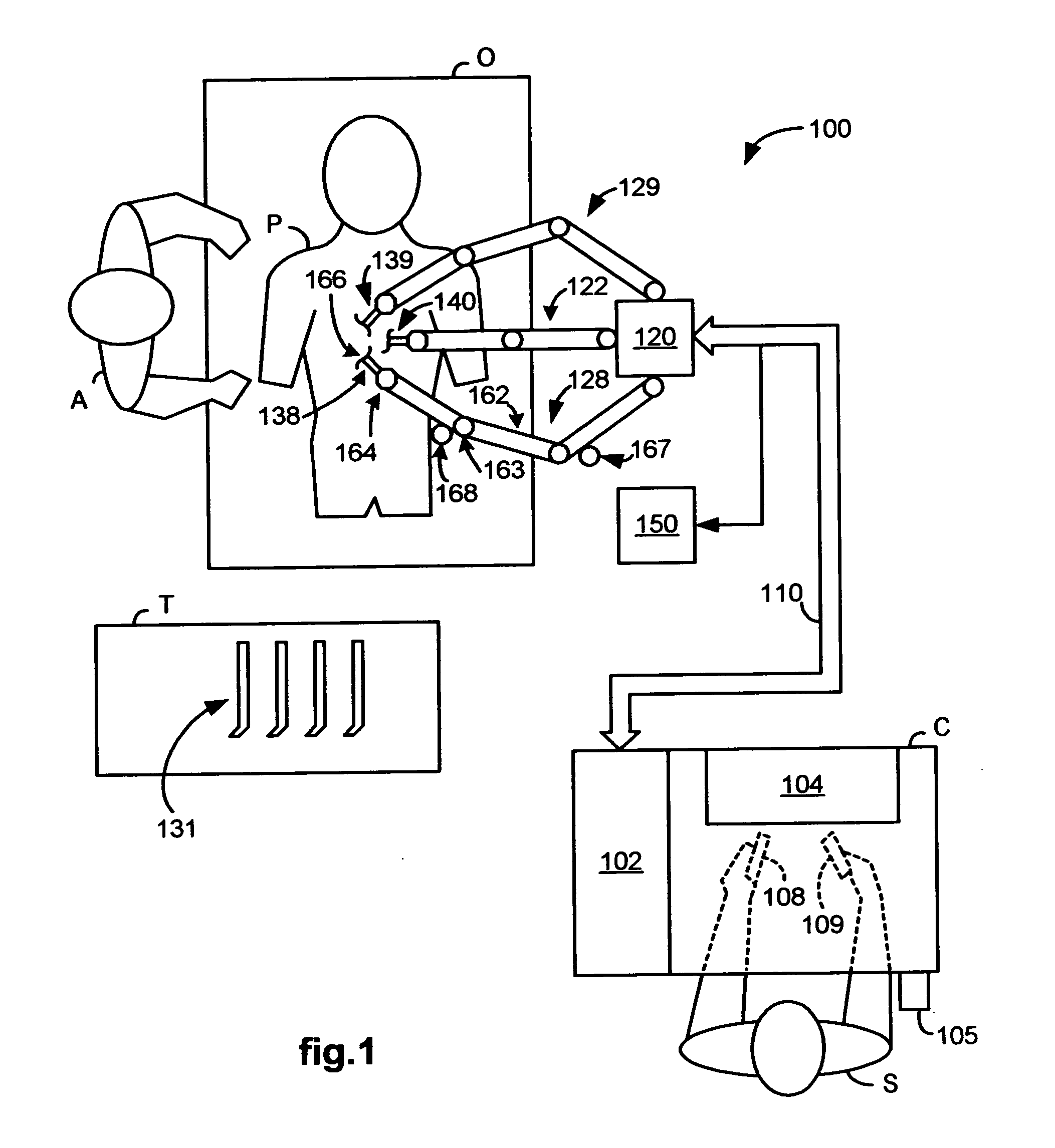
[0025]FIG. 1 illustrates, as an example, a top view of an operating room employing a robotic surgical system. The robotic surgical system in this case is a Minimally Invasive Robotic Surgical (MIRS) system 100 including a Console (“C”) utilized by a Surgeon (“S”) while performing a minimally invasive diagnostic or surgical procedure, usually with assistance from one or more Assistants (“A”), on a Patient (“P”) who is lying down on an Operating table (“O”).

[0026]The Console includes a monitor 104 for displaying an image of a surgical site to the Surgeon, one or more manipulatable master manipulators 108 and 109 (also referred to herein as “control devices” and “input devices”), and a controller 102. The control devices 108 and 109 may include any one or more of a variety of input devices such as joysticks, gloves, trigger-guns, hand-operated controllers, or the like. The controller 102 is a personal computer that may be integrated into the Console or positioned next to it.

[0027]The S...


PUM


Abstract

A robotic control system is placed in clutch mode so that a slave manipulator holding a surgical instrument is temporarily disengaged from control by a master manipulator in order to allow manual positioning of the surgical instrument at a surgical site within a patient. Control systems implemented in a processor compensate for internally generated frictional and inertial resistance experienced during the positioning, thereby making movement more comfortable to the mover, and stabler from a control standpoint. Each control system drives a joint motor in the slave manipulator with a saturated torque command signal which has been generated to compensate for non-linear viscous forces, coulomb friction, cogging effects, and inertia forces subjected to the joint, using estimated joint angular velocities, accelerations and externally applied torques generated by an observer in the control system from sampled displacement measurements received from a sensor associated with the joint.

Description

CROSS REFERENCE TO RELATED APPLICATIONS[0001]This application claims priority to U.S. provisional application Ser. No. 60 / 751,916 filed Dec. 20, 2005, which is incorporated herein by reference.FIELD OF THE INVENTION[0002]The present invention generally relates to robotic surgical systems and in particular, to a control system used in a robotic surgical system for reducing internally generated frictional and inertial resistance to manual positioning of a surgical manipulator.BACKGROUND OF THE INVENTION[0003]Robotic surgical systems such as those used in performing minimally invasive surgical procedures offer many benefits over traditional open surgery techniques, including less pain, shorter hospital stays, quicker return to normal activities, minimal scarring, reduced recovery time, and less injury to tissue. Consequently, demand for minimally invasive surgery using robotic surgical systems is strong and growing.[0004]To perform a minimally invasive surgical procedure on a patient, ...

Claims


Application Information

Patent Timeline
Patent Type & Authority Applications(United States)
IPC IPC(8): A61B17/00
CPCA61B19/22A61B19/2203A61B19/5212A61B2019/2223A61B2019/2288Y10S901/30A61B2019/2207A61B2019/223Y10S901/15Y10S901/28B25J9/1638A61B34/32A61B34/75A61B34/70A61B90/361A61B34/37A61B34/35G05B2219/41213G05B2219/41426B25J9/1641B25J9/1689Y10S901/02A61B34/30
Inventor PRISCO, GIUSEPPE M.LARKIN, DAVID Q.NOWLIN, WILLIAM C.
Owner INTUITIVE SURGICAL OPERATIONS INC
Learn More