Metalwood type golf clubhead having an improved structural system for reduction of the cubic centimeter displacement and the elimination of adverse aerodynamic drag effect

a golf clubhead and metalwood technology, applied in the field of golf clubheads, can solve the problems of reducing the effective ball-contact hitting area of the shaped clubhead, and the subtle changes of the clubhead and the expected performance of the larger metalwood clubhead, so as to reduce the negative drag effect of the conventional shaped clubhead and reduce the cubic centimeter displacement

Inactive Publication Date: 2005-01-13
ANTONIOUS ANTHONY J
View PDF0 Cites 111 Cited by
  • Summary
  • Abstract
  • Description
  • Claims
  • Application Information

AI Technical Summary

Benefits of technology

[0008] The present invention relates to wood-type metalwood golf clubheads having a concave structural innovation system that substantially reduces the cubic-centimeter displacement of the clubhead. In addition, the concave structural system design also reduces the negative drag effects of conv

Problems solved by technology

Although these traditional shaped clubheads are substantially enlarged overall, with higher face heights and wider, bulkier convex shaped crowns and convex shaped sole bottoms, their traditional shaped clubfaces continue to have diminishing and lesser effective ball-contact hitting area, in a heel to toe direction, or top to bottom direction They are not structurally designed to expand the ball-striking area on the clubface proportionately to the overall enlarged clubheads for any possible improved performance, for most golfers.
However, for most golfers, the subtle changes to the clubfaces and the expected performance of the larger metalwood clubheads, have been disappointing.
Fo

Method used


Image

  • Metalwood type golf clubhead having an improved structural system for reduction of the cubic centimeter displacement and the elimination of adverse aerodynamic drag effect
  • Metalwood type golf clubhead having an improved structural system for reduction of the cubic centimeter displacement and the elimination of adverse aerodynamic drag effect
  • Metalwood type golf clubhead having an improved structural system for reduction of the cubic centimeter displacement and the elimination of adverse aerodynamic drag effect

Examples


first embodiment

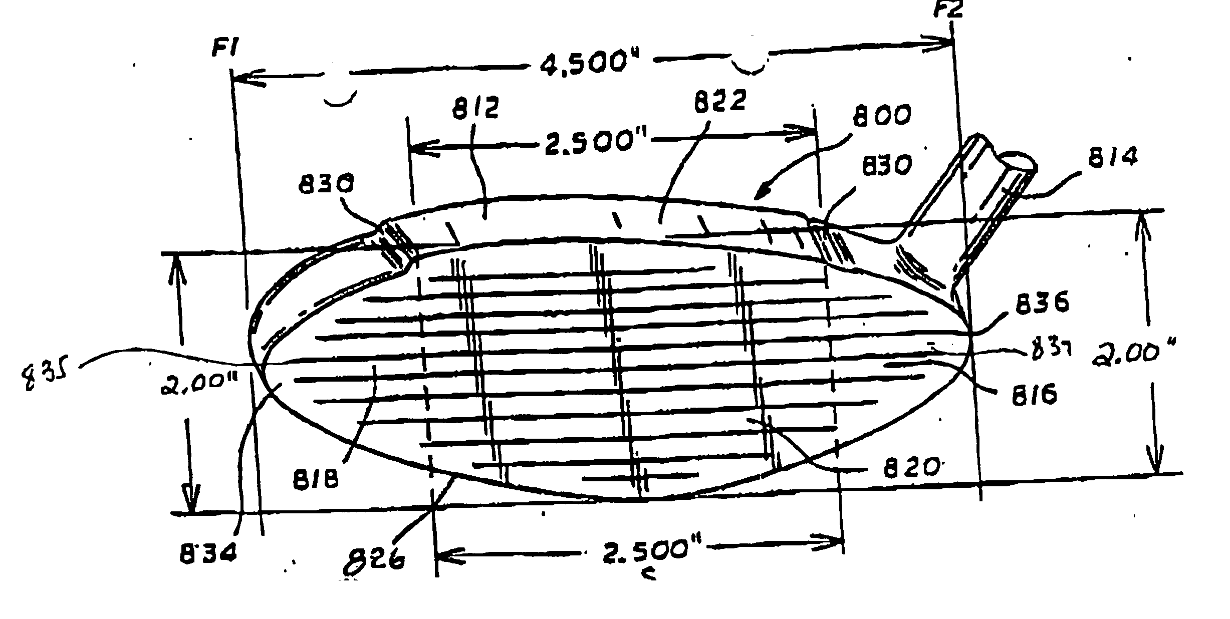
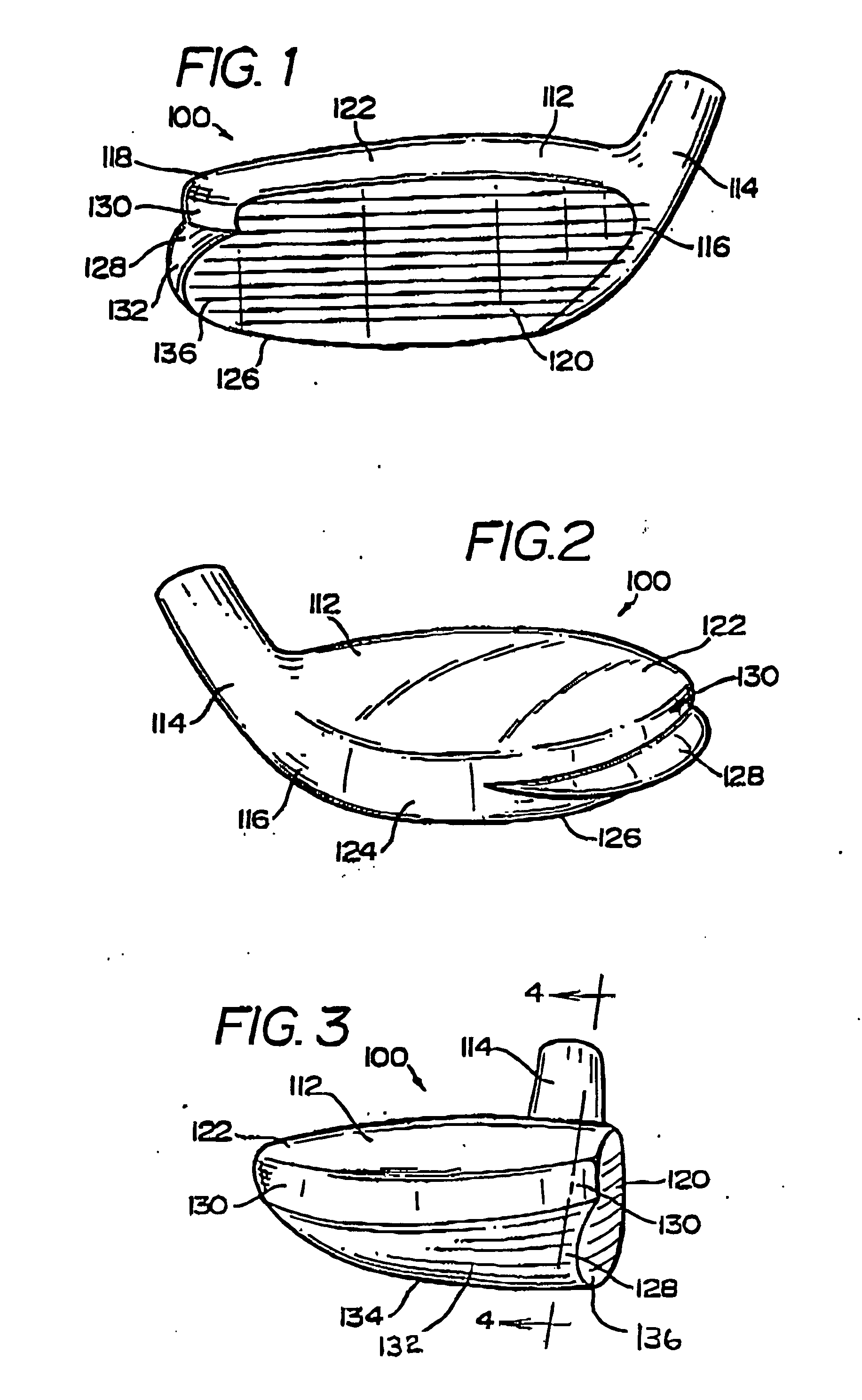
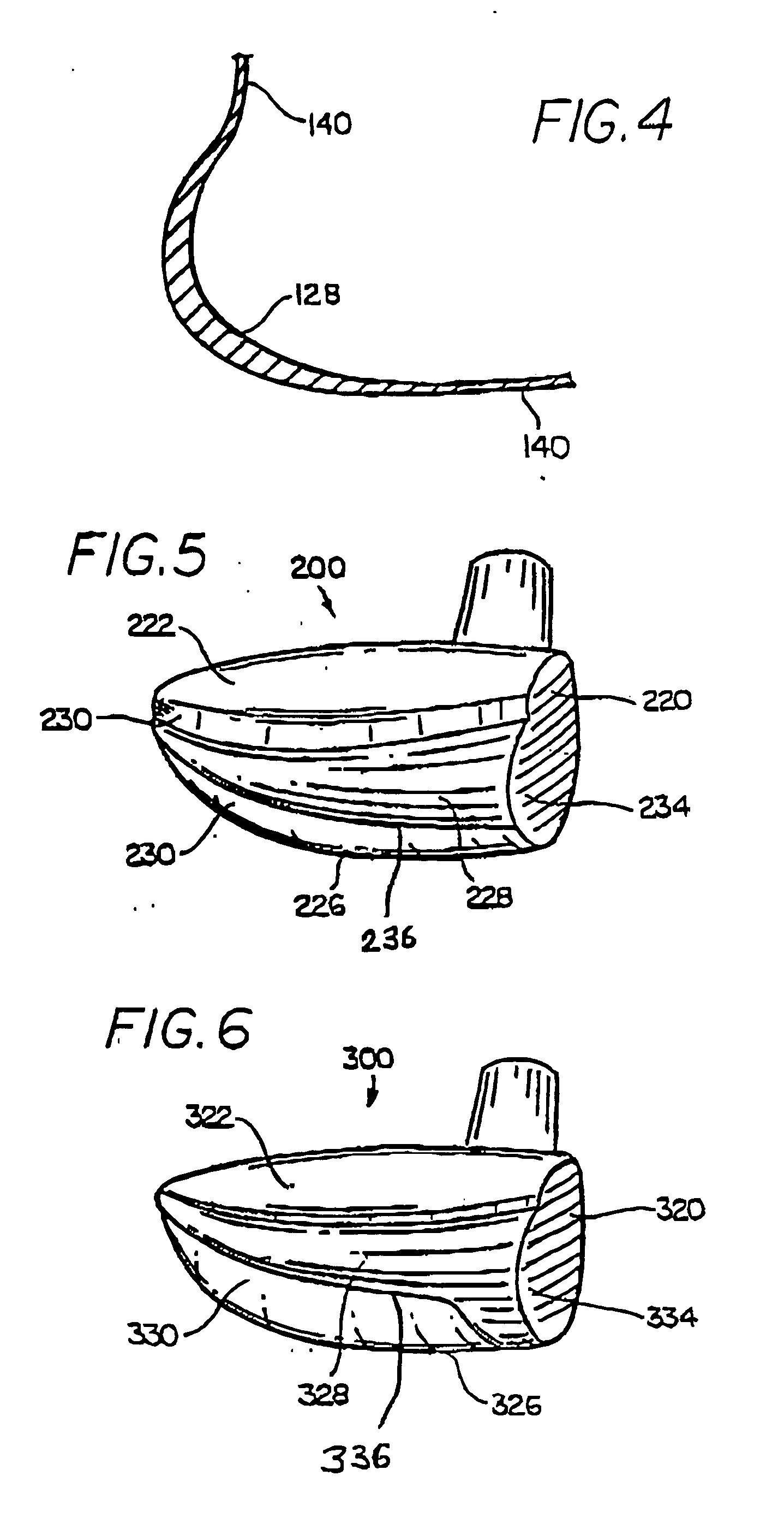
[0091]FIGS. 1-4 show a golf clubhead 100 in accordance with the present invention including a clubhead body 112, hosel 114, heel 116, toe 118, ball-striking clubface 120, upper surface 122, rear surface 124 and bottom sole 126. A single reinforcing and stabilizing member 128 having an aerodynamic shape, is located coincident with or adjacent to the bottom surface 126 of the clubhead 100 and which wraps partially around the peripheral sides 130 of the clubhead 100. The member 128 includes upwardly curving, convex parabolic surface 132 including a lower surface 134 extending upwardly and coincident with the bottom sole 126 of the clubhead 100. In this embodiment, the member 128 has an additional front ball-striking surface 136 which is laterally coincident with the lower section of the ball-striking clubface 120, thereby enlarging the ball contact surface of 120 and providing a greater margin for error when golf balls are struck away from the center of the ball-striking clubface 120 t...

second embodiment

[0093]FIG. 5 illustrates a golf clubhead 200 of the present invention. In this embodiment a reinforcing and stabilizing member 228 includes a ball-striking surface 234 which is parallel to but does not align fully with clubface 220 with a non-coincident raised bottom surface 236 is centrally located on the side wall 230 of the clubhead 200 approximately midway between the crown surface 222 and the bottom 226 of the clubhead 200.

third embodiment

[0094]FIG. 6 illustrates a golf clubhead 300 of the present invention wherein a reinforcing and stabilizing member 328 includes a larger ball-striking surface 334 which is coincident with and covers a larger portion of clubface 320. The reinforcing and stabilizing member 328 has a non-coincident lower surface 336 raised above the bottom surface 326 of the club head 300. The reinforcing and stabilizing member 328 is also located adjacent the top surface of side wall 330 adjacent the crown surface 322 of the clubhead 300. For lower ball flight trajectory, a larger ball-striking surface 334 is coincident with a greater portion of the front of ball-striking clubface 320.


PUM


Abstract

A metalwood type golf clubhead, including a clubhead body having a toe, heel, top crown surface, bottom sole surface, side surfaces, rear surface and ball-striking clubface, having an inwardly disposed lower surface located between the bottom sole surface and the top crown surface. The inwardly disposed lower structure provides improved weight distribution for better balance, additional strength and stability to clubhead and considerably decreases the overall cc displacement and overall weight/mass at the bottom of the clubhead without decreasing the size of the ball striking face and/or the upper top crown surface.

Description

RELATED APPLICATIONS [0001] The present application is a continuation-in-part of application Ser. No. 10 / 165,947 filed Jun. 11, 2002 titled Metalwood Type Golf Club Head Having Expanded Sections Extending the Ball Striking Clubface.BACKGROUND OF THE INVENTION [0002] The present invention relates to the golf clubheads shown and described in my prior U.S. Pat. Nos. 5,954,595, 5,989,134 and 6,530,847 which are incorporated herein by reference, and in particular, to an improved metalwood type golf clubhead having an improved structural system for reduction of cubic centimeter displacement and the elimination of adverse aerodynamic drag effect. [0003] In the aforementioned applications, metalwood type golf club heads are described having at least a reinforcing and stabilizing, hereinafter R / S member, including additional ball-striking surfaces, coincident with and parallel to the clubface and are located horizontally at the toe and heel sections of the clubface, enlarging it substantiall...

Claims


Application Information

Patent Timeline
IPC IPC(8): A63B53/04A63B59/00
CPCA63B53/0466A63B2059/0011A63B2053/0437A63B2053/0433A63B2225/01A63B60/00A63B53/0437A63B53/0433A63B60/006
Inventor ANTONIOUS, ANTHONY J.
Owner ANTONIOUS ANTHONY J
Why Eureka
Try Eureka