Method for determining whether a component holder is defective

a component holder and component technology, applied in the field of determining whether a component holder is defective, can solve problems such as inability to recognize, and achieve the effect of preventing interference and preventing interference between the component holder and the image-picking devi

Active Publication Date: 2008-12-02
PANASONIC CORP
View PDF14 Cites 17 Cited by
  • Summary
  • Abstract
  • Description
  • Claims
  • Application Information

AI Technical Summary

Benefits of technology

[0005]The present invention is developed to solve the above-described problems, and has for its object to provide a device and a method for detecting whether or not a component holder is good, and an apparatus and a method for mounting components with the detecting device, which enable detecting a component holder that affects correct recognition of components and moreover enable preventing interference between constituent devices.
[0035]In addition to measuring the luminance, image-pickup information of the component hold face is taken into account, so that accuracy of determining whether or not the component holder is good is improved further.
[0037]In the component mounting apparatus of the third aspect and the component mounting method of the fourth aspect of the present invention, there is provided the detecting device of the first aspect and the detecting method is performed, whereby contamination of the component hold face of the component holder, peeling off of a coating, and the like can be detected before the component is held. Accordingly, wrong recognition of the component, as a result of reflection at the component hold face during a component recognition operation performed before the component is mounted, can be reduced.
[0038]The component load and transfer device is provided with the detecting device supporter and the drive unit. A need of moving the component load and transfer device to a position where the recognizer is disposed as in the conventional art is eliminated at a recognition time of components held by the component holders. A mounting cycle time is thus shortened and availability in mounting components is increased consequently.
[0041]Moreover, the trigger signal generator is installed, and the component load and transfer device is provided with the position detector. While the image-pickup device moves along the arrangement direction of component holders, downward movement of a component holder can be stopped when the image-pickup device is located below a descending component holder, thus enabling preventing interference between the component holder and the image-pickup device.
[0042]In addition, in the component mounting method of the fourth aspect, a position of the moving image-pickup device is detected, and downward movement of the component holder is controlled on basis of this detected position. Therefore, the downward movement of the component holder can be stopped if the image-pickup device is below the descending component holder. Interference between the component holder and the image-pickup device can be prevented accordingly.

Problems solved by technology

In consequence, if the electronic component 2 is small relatively to the suction face of the suction nozzle 1 as referred to above, the recognizer 5 detects reflecting light from the suction face of the suction nozzle 1 unfavorably, which leads to a problem in that a position of the electronic component 2 cannot be recognized correctly or the suction nozzle 1 is mistakenly recognized as holding the electronic component 2 although the suction nozzle 1 does not suck the electronic component 2.

Method used


Image

  • Method for determining whether a component holder is defective
  • Method for determining whether a component holder is defective
  • Method for determining whether a component holder is defective

Examples


Embodiment Construction

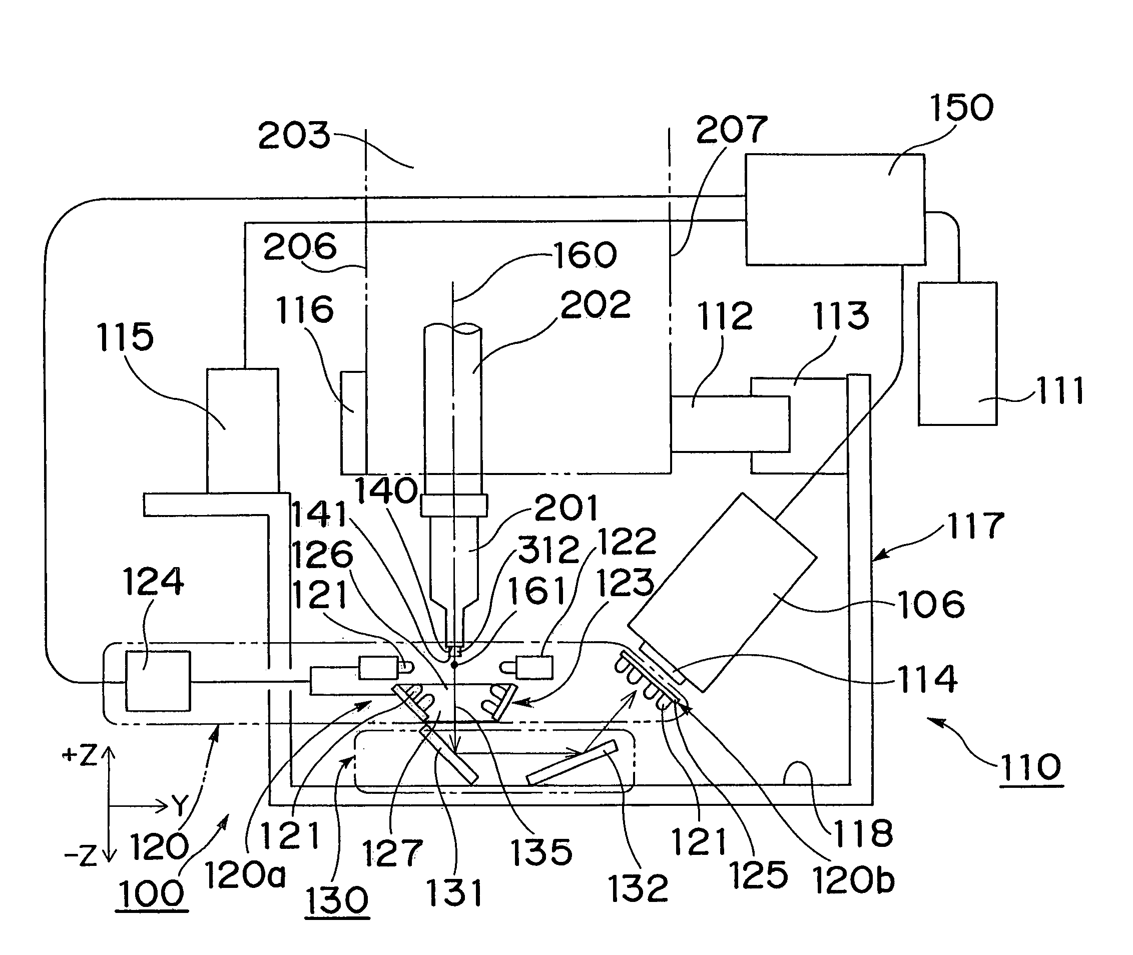
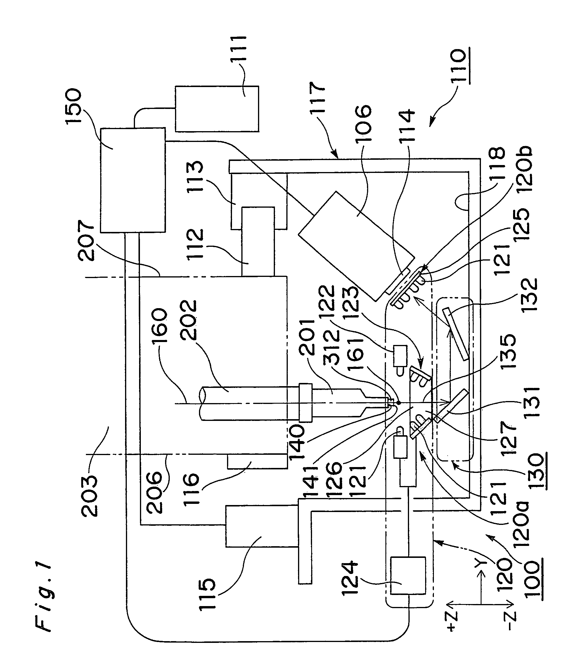
[0069]A device and a method for detecting whether or not a component holder is good, and an apparatus and a method for mounting components according to preferred embodiments of the present invention will be described in detail with reference to the attached drawings. The method for detecting whether or not the component holder is good is a detection method performed by the device for detecting whether or not the component holder is good, the component mounting apparatus is a mounting apparatus with the detecting device, and the component mounting method is a mounting method performed by the component mounting apparatus. Like parts are designated by like reference numerals throughout the drawings.

[0070]The component mounting apparatus with the detecting device will be described first. As shown in FIG. 5, a component mounting apparatus 300 fundamentally comprises a detecting device 100 to be detailed later for detecting whether or not a component holder is good, a component supply dev...


PUM

PropertyMeasurementUnit
angleaaaaaaaaaa
traveling angleaaaaaaaaaa
angleaaaaaaaaaa

Abstract

The present invention provides a device and a method for determining whether or not a component holder is good, which enable detecting component holders that are to affect correct component recognition and further enable preventing interferences between constituent devices, a component mounting apparatus with the determining device, and a component mounting method. The determining device has an illuminating device, a CCD camera and a controller to determine whether or not a suction nozzle is good based on luminance at a component hold face of the suction nozzle. The suction nozzle having light reflectance of the component hold face increased to a level whereat a correct recognition of an electronic component held by the suction nozzle is affected, can be detected accordingly. An interference preventing device is also provided, so that interference between the CCD camera and the suction nozzle can be prevented.

Description

TECHNICAL FIELD[0001]The present invention relates to a device and a method for detecting whether or not a component holder for holding, for instance, an electronic component or the like, is good, and an apparatus and a method for mounting components with the detecting device.BACKGROUND ART[0002]Conventionally, as shown in FIG. 25, in a component mounting apparatus 10 for mounting electronic components 2 onto a circuit board 3, after electronic component 2 is sucked to a suction face at a leading end of a suction nozzle 1, the electronic component 2 held by the suction nozzle 1 passes over an illuminating device 4 during a time while the electronic component is moved to the circuit board 3. The illuminating device 4 illuminates a lower face of the electronic component 2 from below the electronic component 2 held by the suction nozzle 1, and a recognizer 5 performs an image-pickup operation of the electronic component 2 by reflecting light from the lower face. On basis of this image-...

Claims


Application Information

Patent Timeline
Patent Type & Authority Patents(United States)
IPC IPC(8): H05K3/30H05K13/04H05K13/08
CPCH05K13/0408H05K13/08Y10T29/49131Y10T29/4913H05K13/0409H05K13/0812
Inventor KAWASE, TAKEYUKIKINO, TOSHIYUKIYOSHITAKE, TAKANORISANO, KIMIAKIHATTORI, YOSHIYUKIYAZAWA, TAKASHIUCHIYAMA, HIROSHITANAKA, YOUICHIIMAFUKU, SHIGEKIKANETAKA, IWAOOGURA, TAMAKI
Owner PANASONIC CORP
Why Eureka
Try Eureka