
Twist lock ring binder

a technology of twist lock and ring, which is applied in the field of twist lock ring binder, can solve the problems of not readily rotating the ring open position, and achieve the effects of not readily rotating, easy to separate the ring halves, and not readily rotating

Inactive Publication Date: 2008-12-09
U S RING BINDER CORP
View PDF8 Cites 3 Cited by
  • Summary
  • Abstract
  • Description
  • Claims
  • Application Information

AI Technical Summary

Benefits of technology

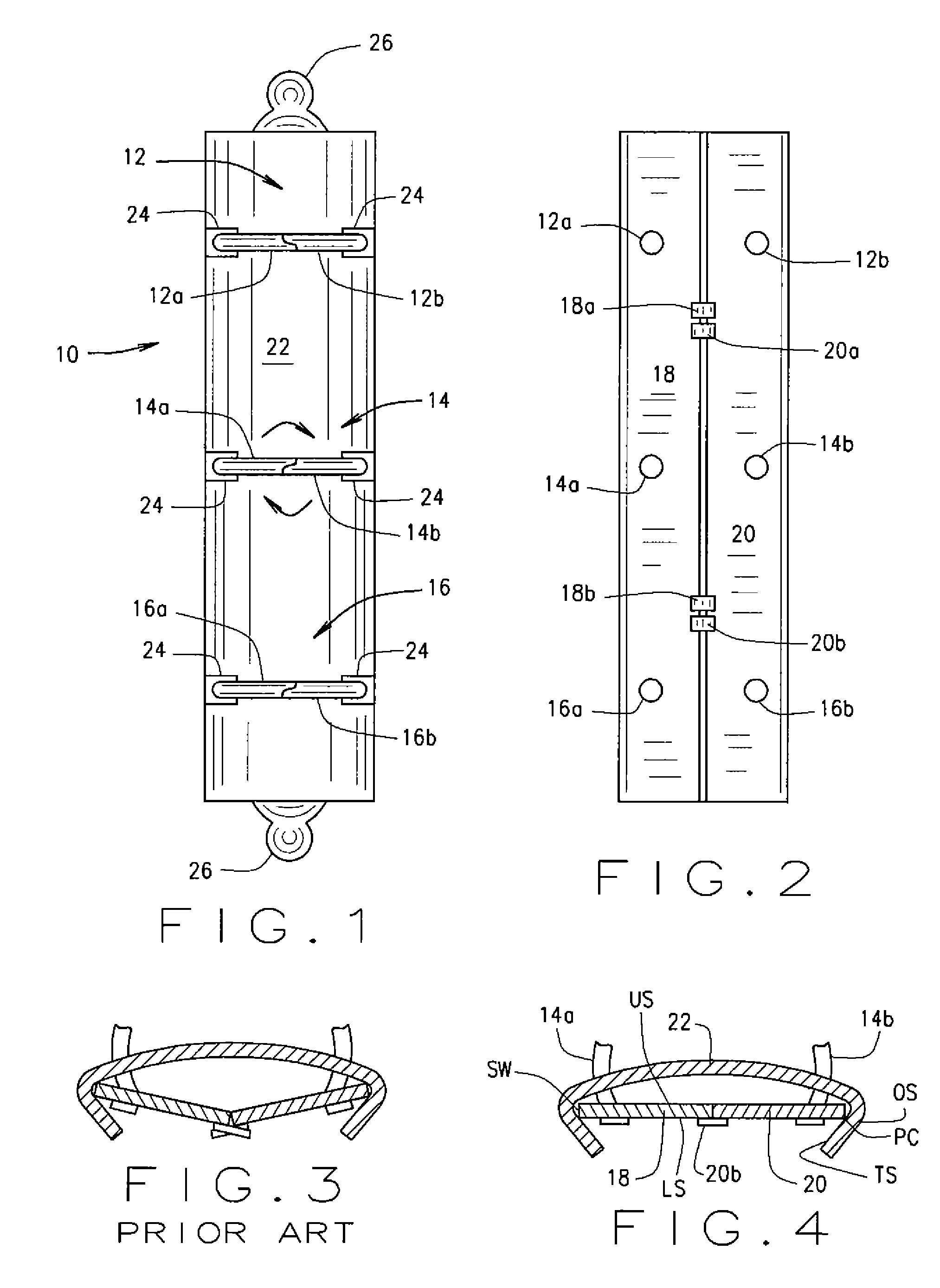
[0006]A user opens the binder by exerting finger pressure on one of the rings. The openings in the shield through which the ring halves extend are wider than the diameter of a ring half to make it easier to separate ring halves and open the binder. However, the leaves and their associated swedges are at a shallow angle with respect to each other, the leaves do not readily rotate to a ring open position if the binder is dropped or bumped. The result is a ring metal readily opened by the exertion of finger pressure on a binder ring, but not when the binder is bumped or dropped.

Problems solved by technology

However, the leaves and their associated swedges are at a shallow angle with respect to each other, the leaves do not readily rotate to a ring open position if the binder is dropped or bumped.

Method used


Image

  • Twist lock ring binder
  • Twist lock ring binder
  • Twist lock ring binder

Examples


Embodiment Construction

[0016]The following detailed description illustrates the invention by way of example and not by way of limitation. This description will clearly enable one skilled in the art to make and use the invention, and describes several embodiments, adaptations, variations, alternatives and uses of the invention, including what I presently believe is the best mode of carrying out the invention. As various changes could be made in the above constructions without departing from the scope of the invention, it is intended that all matter contained in the above description or shown in the accompanying drawings shall be interpreted as illustrative and not in a limiting sense.

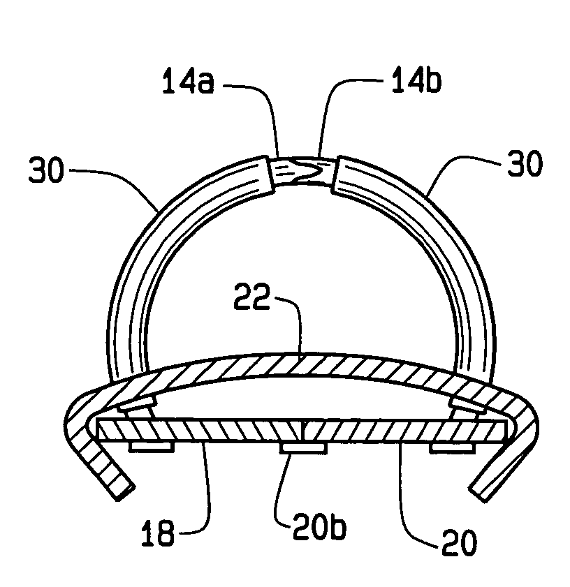
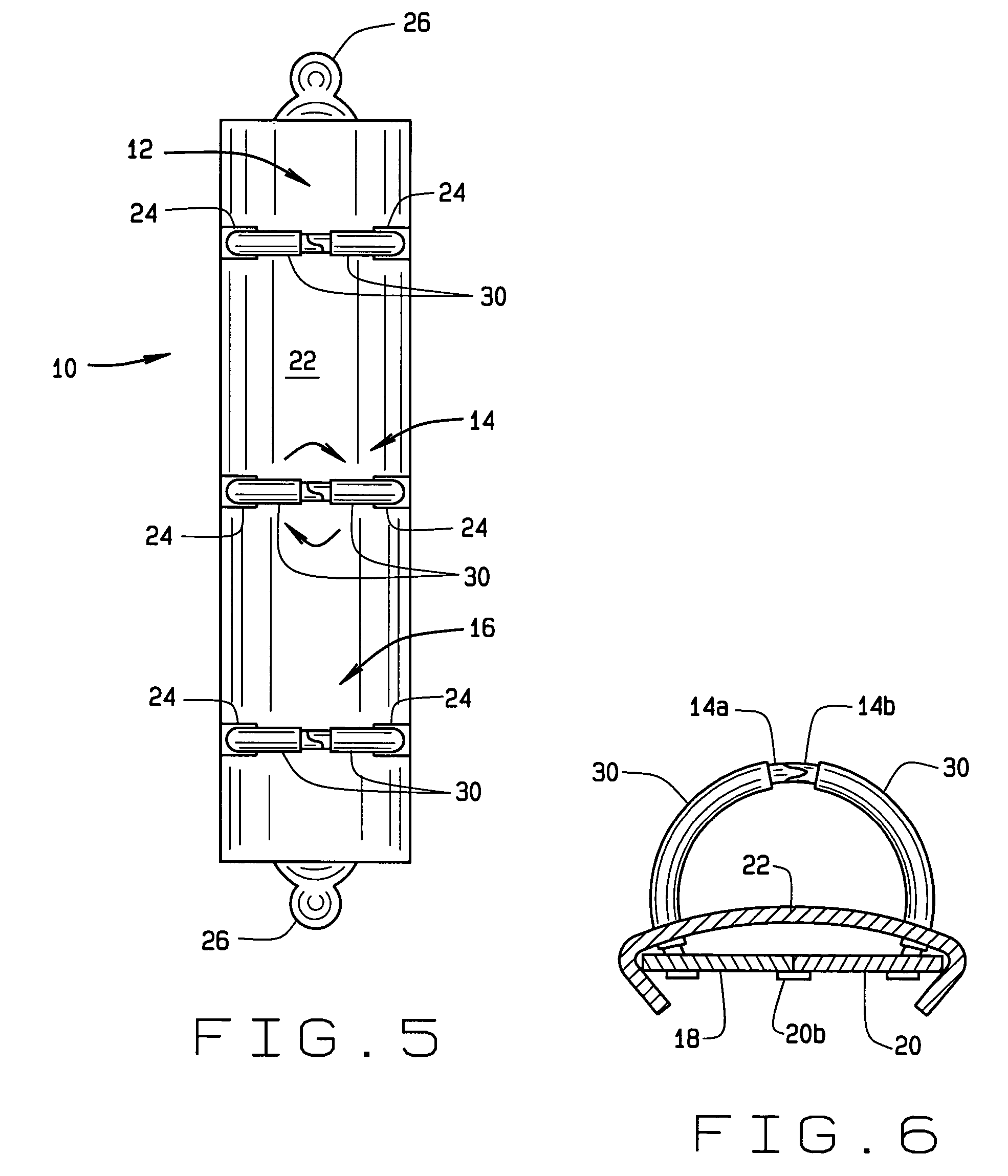
[0017]Referring to the drawings, a binder ring metal 10 of the present invention is for installation in a binder (not shown) for holding hole punched sheets of paper or the like. Ring metal 10 is a “twist-lok” metal having a plurality of binder rings indicated generally 12, 14, and 16. The metal may have more, or fewer, rings ...


PUM


Abstract

An improved “twist-lok” binder ring metal 10 includes binder rings (12-16) comprised of pairs of binder ring halves having an end attached to leaves (18, 20). Each leaf has swedges (18a, 18b, 20a, 20b) are spaced along the length of the metal. A cover (22) fitting over the leaves has spaced openings (24) through which ring halves extend. The cover and leaves only have a point contact with each other, and the leaves extend away from the cover at a relatively shallow angle.The binder is opened by someone exerting finger pressure on one of the rings and twisting the ring halves apart. Because of the shallow angle of the leaves with respect to each other, the leaves do not readily rotate to a ring open position if the binder is dropped or bumped. The result is a ring metal readily opened by use of finger pressure on a binder ring, but which will not open if the binder is bumped or dropped.

Description

CROSS REFERENCE TO RELATED APPLICATIONS[0001]NoneSTATEMENT REGARDING FEDERALLY SPONSORED RESEARCH OR DEVELOPMENT[0002]N / ABACKGROUND OF THE INVENTION[0003]In U.S. Pat. No. 5,660,490, there is described a binder ring metal commonly referred to as a “twist-lok” metal. An advantage of this type metal is that it is relatively easy for a user to open by applying finger pressure to respective halves of a binder ring, typically near the respective ends of the ring halves where they join together to close the metal. The user then moves his or her fingers in a rotary or twisting manner to separate the ends of the halves. The opposite ends of the ring halves are connected to separate leaves which extend side-by-side beneath a cover portion of the metal. The leaves have swedges which are angled with respect to the leaves and the twisting movement of the upper portion of the ring halves causes the leaves to sufficiently flex so that an over center toggling action occurs and the binder rings rema...

Claims


Application Information

Patent Timeline
Patent Type & Authority Patents(United States)
IPC IPC(8): B42F3/02B42F13/02
CPCB42F13/22B42P2241/00
Inventor WHALEY, PAUL
Owner U S RING BINDER CORP
Learn More