
Floating gate field effect transistors for chemical and/or biological sensing

a field effect transistor and transistor technology, applied in the field of biological and/or chemical sensing, can solve the problems of limited use as gas sensors, limited application in liquid/fluent solid measurement, and limited use of organic fets as gas sensors,

Active Publication Date: 2008-12-09
POLYTECHNIC INSTITUTE OF NEW YORK UNIVERSITY
View PDF0 Cites 187 Cited by
  • Summary
  • Abstract
  • Description
  • Claims
  • Application Information

AI Technical Summary

Problems solved by technology

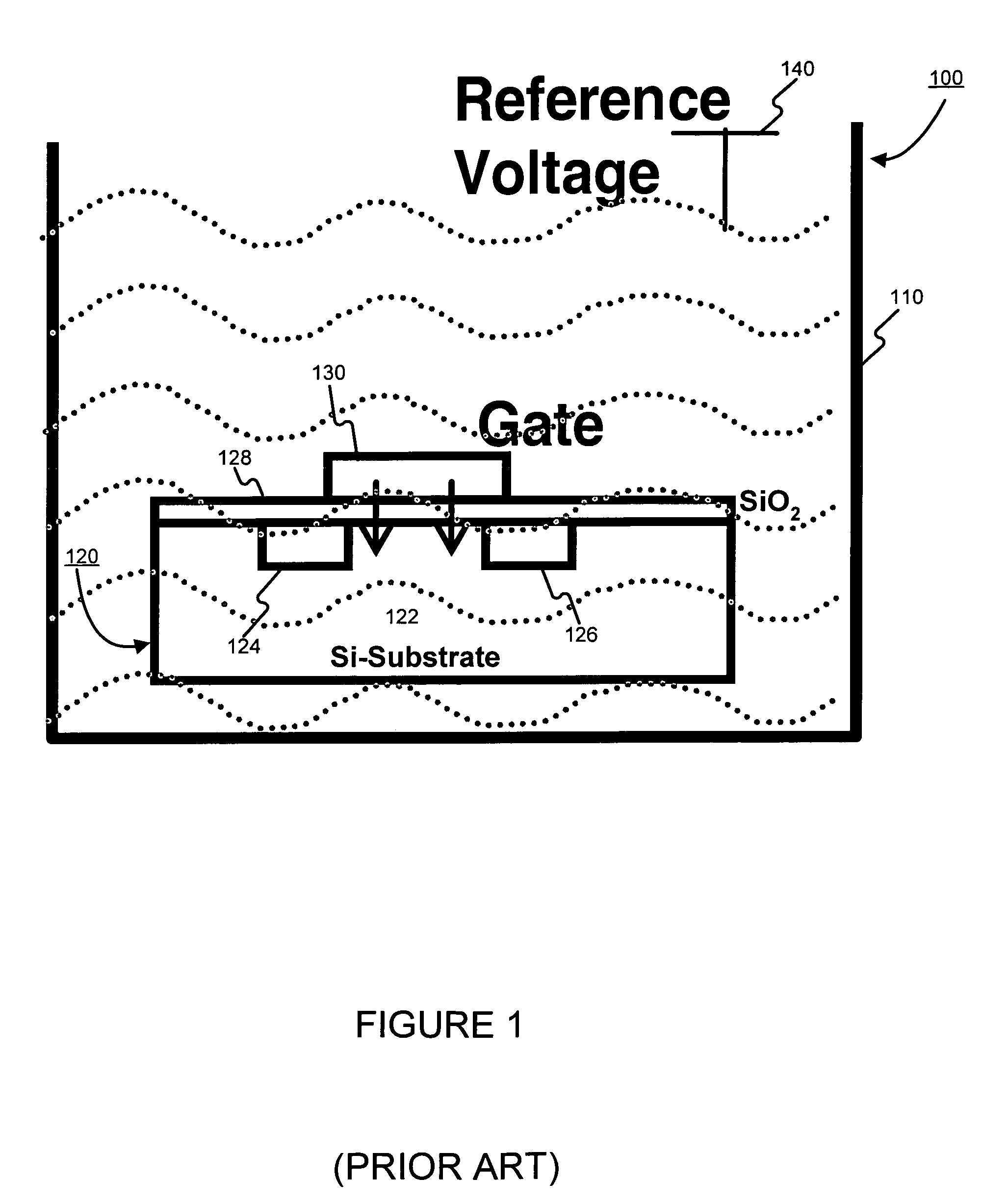
Although conventional Si-based ISFETs can sense various types of targets, there are some limitations that prevent their widespread deployment.
Due to this reference electrode-based biasing scheme, these ISFETs are suitable as pH sensors, but they have limited use as gas sensors.
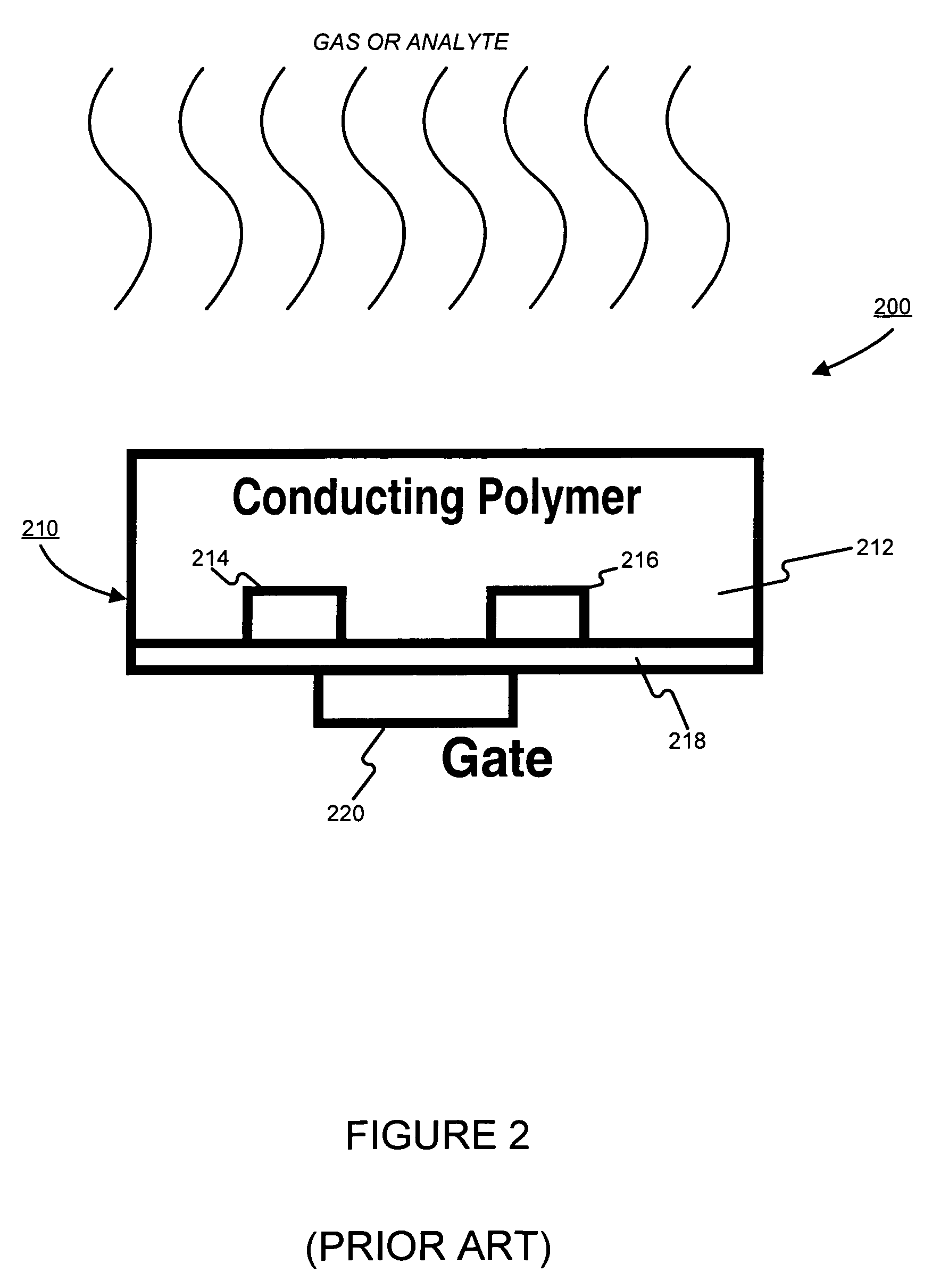
Unfortunately, organic FETs generally have a much lower drive current compared to bulk silicon devices.
It is also difficult to integrate on-chip bias and peripheral circuits with organic FETs, and they are not as easily miniaturizable as silicon FETs.

Method used


Image

  • Floating gate field effect transistors for chemical and/or biological sensing
  • Floating gate field effect transistors for chemical and/or biological sensing
  • Floating gate field effect transistors for chemical and/or biological sensing

Examples


first embodiment

§ 4.1 FIRST EMBODIMENT

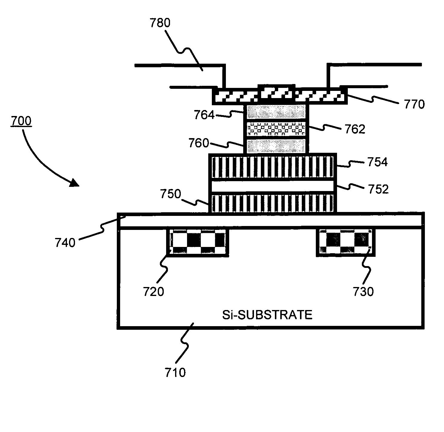
[0030]FIG. 3 illustrates a cross sectional view of an exemplary floating gate ion sensitive field effect transistor 300 (FGISFET), consistent with the present invention, that overcomes at least some of the limitations of conventional and organic ISFETs introduced in § 1.2 above. The exemplary FGISFET 300 may comprise a substrate 310 (which may be silicon-based or organic, for example, though is preferably not organic), a source 320, a drain 330, a first insulating layer (e.g., an oxide layer) 340, a floating gate 342, a second insulating layer (e.g., an oxide layer) 344, a sensing material 348 and a control gate 346. The control gate 346 may be used for setting the sensor's operating point and the floating gate 342 may be used to measure ionic activity associated with a target material. The sensing material 348 may be an ion-sensitive material that may be selected to sense a specific chemical, a specific class of chemicals, a specific biological material, and / o...

second embodiment

§ 4.2 SECOND EMBODIMENT

[0054]§ 4.2.1 Threshold Voltage Measuring Circuit

[0055]FIG. 9 illustrates an exemplary differential amplifier-based read-out circuit 900 for measuring threshold voltage shifts in a manner consistent with the present invention. The circuit 900 may include a differential amplifier 950 for outputting a voltage differential, an FGFET 910 with sensing material, an FGFET 920 without sensing material, resistors 930, 940 and an analog-to-digital converter 960.

[0056]The differential amplifier 950 can output a signal representing a threshold voltage difference between the two FGFETs 910 and 920. The amplified threshold voltage differential signal may be provided as an input to an analog-to-digital converter 960. Lines 970 may provide the digitized signal to a signal processing system (not shown) for translation of the signal to a target material property (e.g., presence, absence, amount, concentration, toxicity, etc.) measurement.

[0057]FIG. 10 illustrates a cross sectio...


PUM

PropertyMeasurementUnit
threshold voltagesaaaaaaaaaa
electric fieldaaaaaaaaaa

Abstract

Specific ionic interactions with a sensing material that is electrically coupled with the floating gate of a floating gate-based ion sensitive field effect transistor (FGISFET) may be used to sense a target material. For example, an FGISFET can use (e.g., previously demonstrated) ionic interaction-based sensing techniques with the floating gate of floating gate field effect transistors. The floating gate can serves as a probe and an interface to convert chemical and / or biological signals to electrical signals, which can be measured by monitoring the change in the device's threshold voltage, VT.

Description

§ 0. RELATED APPLICATIONS[0001]This application claims benefit to U.S. Provisional Application Ser. No. 60 / 535,975, titled “A CMOS-COMPATIBLE ION SENSITIVE FIELD EFFECT TRANSISTOR (ISFET) FOR CHEMICAL AND BIOLOGICAL SENSING” filed on Jan. 12, 2004 and listing Kalle Levon, Ben Zhao, Tsunehiro Sai, and Arifur Rahman as inventors (referred to as “the '975 provisional”). That application is incorporated herein by reference. The scope of the present invention is not limited to any requirements of the specific embodiments described in that application.§ 1. BACKGROUND[0002]§ 1.1 Field of the Invention[0003]The present invention concerns biological and / or chemical sensing. In particular, the present invention concerns floating gate (e.g., silicon or organic) transistors, such as Ion Sensitive Field Effect Transistors (ISFETs) for example, for chemical and / or biological sensing.[0004]§ 1.2 Background Information[0005]The key element of a conventional silicon-based ISFET is a gate capacitor f...

Claims


Application Information

Patent Timeline
Patent Type & Authority Patents(United States)
IPC IPC(8): H01L21/00G01N27/26G01N27/414
CPCG01N27/4148G01N27/4145
Inventor LEVON, KALLERAHMAN, ARIFURSAI, TSUNEHIROZHAO, BEN
Owner POLYTECHNIC INSTITUTE OF NEW YORK UNIVERSITY
Learn More