Adjustable electrical box for flush or offset mounting of electrical devices on brick or stone walls

a technology of electrical boxes and mounting brackets, which is applied in the direction of electrical apparatus casings/cabinets/drawers, coupling device connections, lighting conductor installation, etc., can solve the problems of affecting the attractiveness of the installed box, and affecting the appearance of the box

Active Publication Date: 2008-12-09
ARLINGTON INDS
View PDF12 Cites 32 Cited by
  • Summary
  • Abstract
  • Description
  • Claims
  • Application Information

AI Technical Summary

Benefits of technology

[0014](5) The outlet box and adapter of the present invention provides an aesthetically pleasing electrical box for mounting an electrical device to the exterior of a wall constructed of stone or sim

Problems solved by technology

As a result of the substantial thickness of brick and stone wall coverings and their imperviousness to receive fasteners, conventional electrical boxes cannot easily be mounted to brick and stone walls.
The cement around the periphery is typically visible from the front of the conventional box, and this typically detracts from the attractiveness of the installed box.
Additionally, as a result of using only cement to secure the box, it is difficult to level the box with respect to the outer surface of the stone wall.
An additional

Method used


Image

  • Adjustable electrical box for flush or offset mounting of electrical devices on brick or stone walls
  • Adjustable electrical box for flush or offset mounting of electrical devices on brick or stone walls
  • Adjustable electrical box for flush or offset mounting of electrical devices on brick or stone walls

Examples


Embodiment Construction

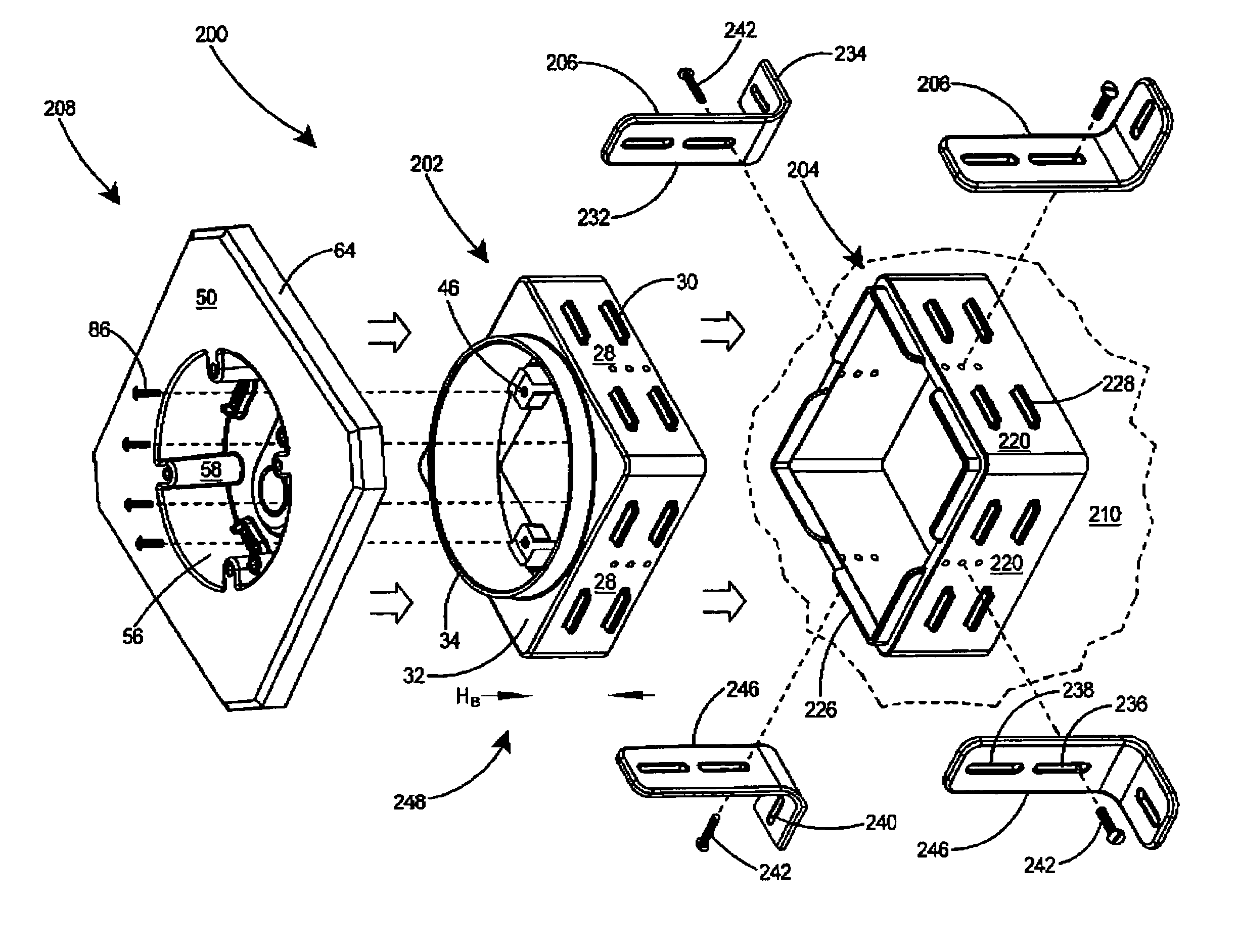
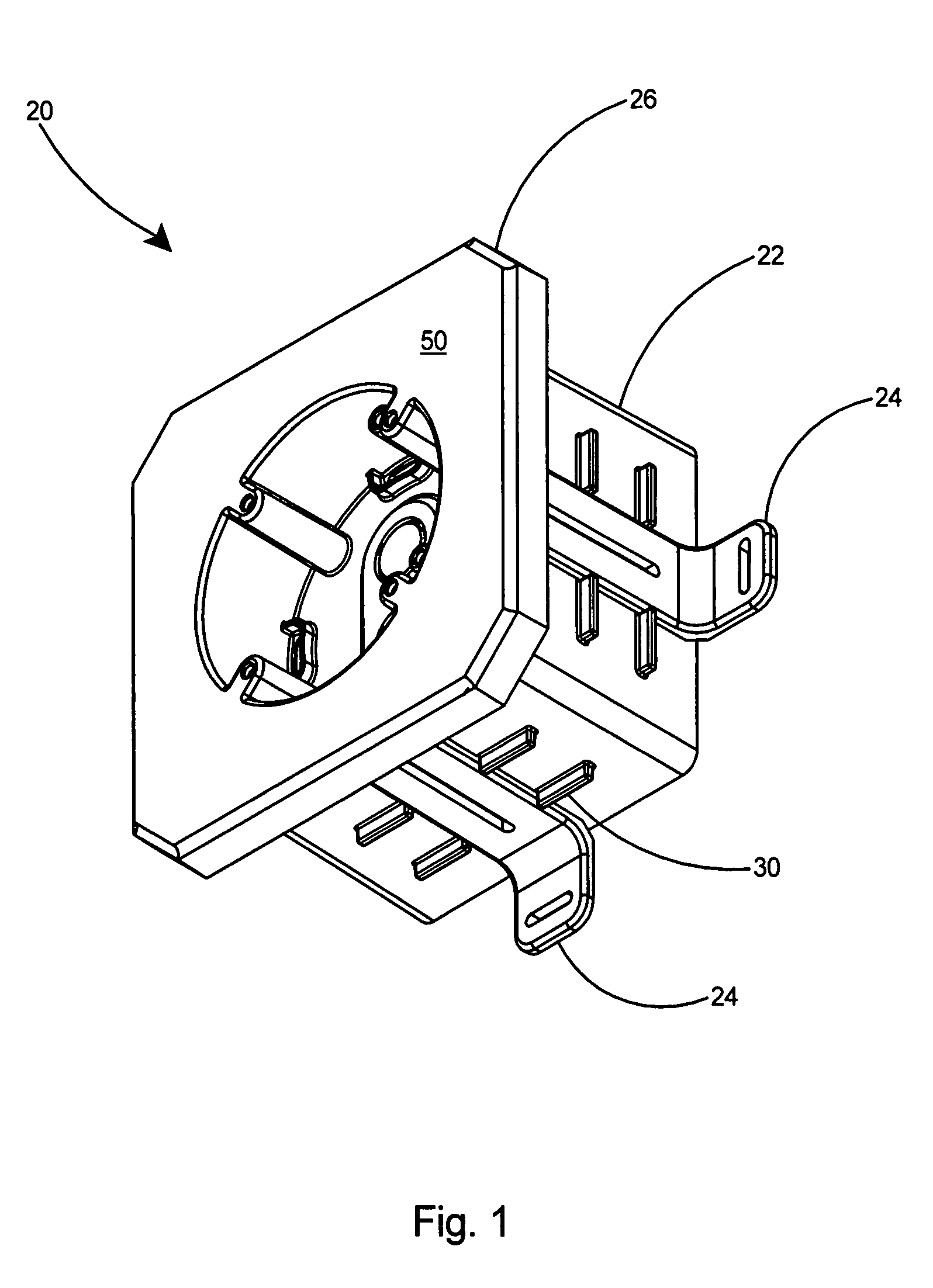
[0049]With reference to FIG. 1, there is shown the first embodiment of the present invention, an adjustable electrical box assembly 20 including a base member 22, one or more anchoring members 24, and an electrical box 26. The adjustable electrical box assembly 20 can be used to mount an electrical device to a brick or stone wall (not shown), either flush with the wall or at a predetermined offset based on the user's preference.

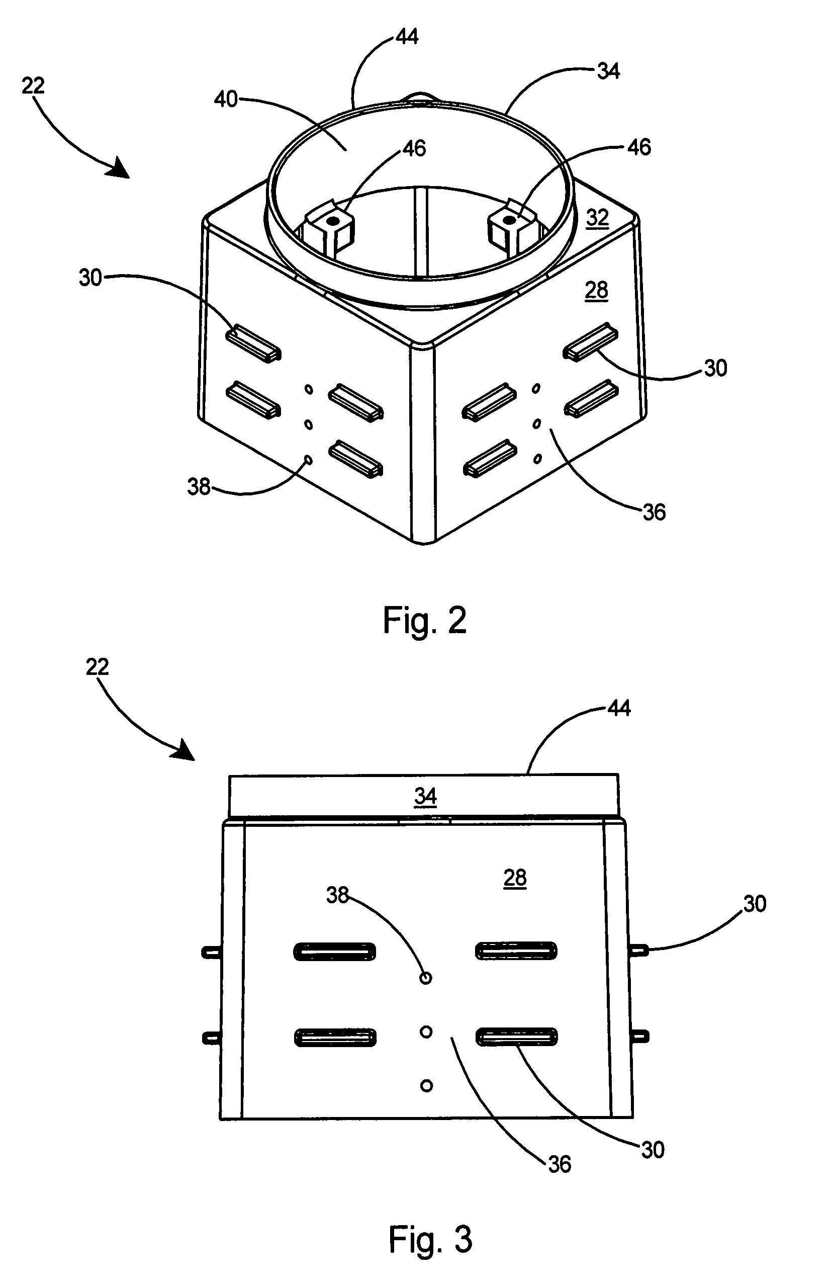
[0050]Referring to FIGS. 2 and 3, the base member 22 includes sidewalls 28, a plurality of outward extending tabs 30, a top wall 32, and a lip 34 extending from the top wall 32. The outward extending tabs 30 are arranged in pairs along each sidewall 28 of the base member 22 thereby defining a gap 36 there between. A plurality of apertures 38 is provided in linear alignment longitudinally along the sidewall 28 of the base member 22 within the gap 36. The lip 34 includes an inner periphery 40, an inner edge 42, an outer edge 44, and a plurality of bosses 46 alo...


PUM


Abstract

An adjustable electrical box assembly for mounting an electrical device on a stone wall either flush with the wall or at a desired offset. The assembly includes a base member, anchoring members, an electrical box, and an optional base extender. For a wall constructed of narrow depth stones, the base member is mounted directly to the substrate using the anchoring members. For a wall constructed of thick stones, the base member and base extender are secured together with the anchoring members and the assembly is secured to the substrate. The offset of the electrical box from the wall surface is set by adjusting the position of attachment of the anchoring members with respect to the sidewalls of the base member and base extender. The electrical box is adapted to receive a light fixture or similar electrical device.

Description

[0001]This application is a Continuation-In-Part of U.S. patent application Ser. No. 11 / 821,730 filed Jun. 25, 2007 and still pending, the entire contents of which are incorporated herein by reference.FIELD OF THE INVENTION[0002]This invention relates to electrical junction boxes and specifically to an adjustable electrical box assembly that enables mounting an electrical device to a stone wall in a flush or offset configuration depending on the homeowner's preference.BACKGROUND OF THE INVENTION[0003]Electrical boxes are commonly installed on the exterior walls of buildings to mount electrical fixtures and the like. For the homeowner, it is desirable to have the option of mounting the electrical fixture either flush with the outer wall surface or at some predetermined offset from the wall surface. Conventional electrical boxes typically include attached captive fasteners that enable mounting of the box by driving the fasteners sideways into a stud. Typically the conventional electri...

Claims


Application Information

Patent Timeline
IPC IPC(8): H02G3/08
CPCH02G3/10H02G3/12H02G3/16Y10S248/906
Inventor GRETZ, THOMAS J.
Owner ARLINGTON INDS
Why Eureka
Try Eureka