Thin film magnetic head

a magnetic head and thin film technology, applied in the field of thin film magnetic heads, can solve the problems of unneeded data recording, blurry write, adverse effects on the detection of servo signals or the s/n ratio of reproduction waveforms, etc., and achieve excellent overwrite characteristics

Inactive Publication Date: 2008-12-09
HEADWAY TECH INC +1
View PDF25 Cites 11 Cited by
  • Summary
  • Abstract
  • Description
  • Claims
  • Application Information

AI Technical Summary

Benefits of technology

[0011]It is an object of the present invention to provide a perpendicular recording type thin film magnetic head having a configuration which can provide the excellent overwrite characteristics and a manufacturing method thereof, a magnetic head apparatus and a magnetic disk apparatus.
[0013]As described above, in the thin film magnetic head according to the present invention, the upper yoke magnetic pole film is connected to the side of the main magnetic pole film close to the write shield film. That is, the yoke magnetic pole film is connected to the upper side of the main magnetic pole film, and it is different from the conventional configuration in which the yoke magnetic pole film is connected to the lower side of the main magnetic pole film distanced from the write shield film. According to the above-described configuration, in the thin film magnetic head, the upper yoke magnetic pole film having a large magnetic charge can be arranged in the vicinity of the ABS, thereby increasing the magnetic charge in the vicinity of the ABS. Therefore, the thin film magnetic head with the excellent overwrite characteristics can be obtained.
[0014]Another important point of the present invention lies in that the end portion on the ABS side in the upper yoke magnetic pole film is retracted in a direction apart from the ABS in accordance with an increase in film thickness which is measured from the surface of the main magnetic pole film. According to this configuration, since an interval between the end portion of the upper yoke magnetic pole film and the write shield film is increased as distanced from the ABS, the shield end portion of the write shield film facing the magnetic pole end of the main magnetic pole can be prevented from generating the magnetic saturation due to a magnetic flux leaking from the end portion of the upper yoke magnetic pole film.
[0015]Further, since the shield end portion of the write shield film facing the magnetic pole end of the main magnetic pole film can be prevented from generating the magnetic saturation, the end portion of the upper yoke magnetic pole film can be arranged closer to the ABS, thereby further improving the overwrite characteristics.

Problems solved by technology

If the write capability is high in a magnetic head based on the perpendicular recording scheme (a perpendicular magnetic recording head: which will be referred to as a “PMR” hereinafter), there may occur a problem which is a so-called write blur by which unnecessary data is recorded between adjacent tracks due to generation of this skew angle.
When this write blur is produced, detection of a servo signal or an S / N ratio of a reproduction waveform is adversely affected.
In this type of PMR, however, since the main magnetic pole film is formed after the lower yoke film, the lower yoke film is affected and a neck height appears when forming the main magnetic pole film with the magnetic pole end portion having a bevel shape, and a part having a narrow width corresponding to a track width is extended by a length corresponding to the neck height part, resulting in the possibility of shifting from a designed length.
In order to avoid the influence by shifting of this neck height, the lower yoke film must be formed apart from the ABS, and it is difficult to increase a magnetic charge (which is also referred to as a magnetic volume) at a part close to the ABS.
Therefore, the conventional PMR has a problem that providing the excellent overwrite characteristics is difficult.

Method used


Image

  • Thin film magnetic head
  • Thin film magnetic head
  • Thin film magnetic head

Examples


Embodiment Construction

[0080]1. Thin Film Magnetic Head

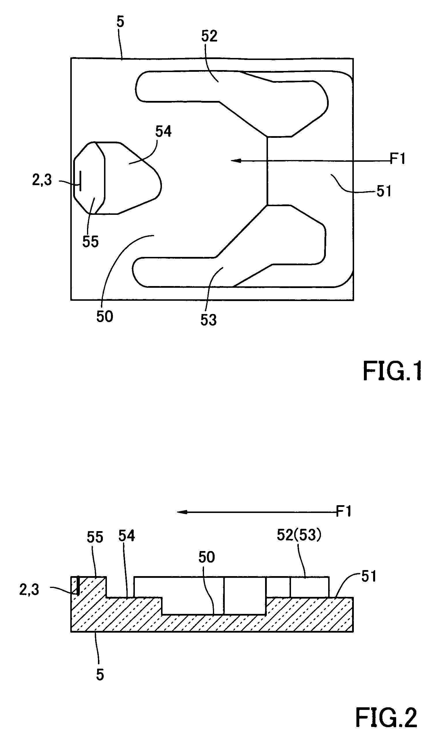
[0081]Referring to FIGS. 1 and 2, a thin film magnetic head according to the present invention includes a slider 5, a recording head 2 and a read element 3. The slider 5 is a ceramic structure consisting of, e.g., Al2O3—TiC or the like. The slider 5 has a geometrical shape for controlling the flying characteristics in an ABS. As a typical example of such a geometrical shape, the drawing shows an example comprising a first step portion 51, a second step portion 52, a third step portion 53, a fourth step portion 54 and a fifth step portion 55 on a base bottom surface 50 on the ABS side. The base bottom surface 50 serves as a negative pressure generating section with respect to a direction of an air flow indicated by an arrow F1, and the second step portion 52 and the third step portion 53 constitute a stepped air bearing rising from the first step portion 51. The surfaces of the second step portion 52 and the third step portion 53 function as the ABS. T...


PUM

PropertyMeasurementUnit
saturation magnetic flux densityaaaaaaaaaa
thicknessaaaaaaaaaa
thicknessaaaaaaaaaa

Abstract

A thin film magnetic head has a configuration in which a main magnetic pole film having a magnetic pole end portion on a medium opposing surface (ABS) side facing a magnetic disk, a write shield film facing the magnetic pole end portion so as to form a recording gap film on the medium opposing surface side, and a thin film coil wound around at least a part of the write shield film are laminated. Further, the thin film magnetic head has an upper yoke magnetic pole film whose size is larger than that of the main magnetic pole film at a part more distant from the ABS than the recording gap film, and this upper yoke magnetic pole film is bonded to the side of the main magnetic pole film close to the thin film coil. In the upper yoke magnetic pole film, an end portion on the ABS side is retracted in a direction apart from the ABS in accordance with an increase in film thickness which is measured from the surface of the main magnetic pole film.

Description

BACKGROUND OF THE INVENTION[0001]1. Field of the Invention[0002]The present invention relates to a thin film magnetic head which performs a magnetic recording operation in a perpendicular recording scheme and a manufacturing method thereof, and to a magnetic head apparatus and a magnetic disk apparatus.[0003]2. Description of the Related Art[0004]In recent years, the surface recording density of a magnetic disk apparatus has been considerably improved. In particular, the surface recording density of a magnetic disk apparatus has recently reached 160 to 200 giga bytes / platter and will further robustly exceeds this value. With this increase, an improvement in performance of a thin film magnetic head has been demanded.[0005]Roughly classifying the thin film magnetic head based on recording schemes, there are a longitudinal recording scheme which records information in an in-recording-surface (longitudinal) direction of a magnetic disk and a perpendicular recording scheme which records ...

Claims


Application Information

Patent Timeline
Patent Type & Authority Patents(United States)
IPC IPC(8): G11B5/31G11B5/147
CPCG11B5/1278G11B5/3116
Inventor SASAKI, YOSHITAKAITOH, HIROYUKIKAMIGAMA, TAKEHIROSHIMIZU, TATSUSHI
Owner HEADWAY TECH INC
Why Eureka
Try Eureka