Device for monitoring the correct operation of a plurality of devices, notably actuators

Active Publication Date: 2011-05-19
THALES SA
View PDF8 Cites 7 Cited by
  • Summary
  • Abstract
  • Description
  • Claims
  • Application Information

AI Technical Summary

Benefits of technology

One advantage of the invention is that the monitoring device is common to a plurality of items of equipment, these items of equipment being equally able to be of the same type as of heterogeneous types.
Another advantage of the invention is that the monitoring device imposes no additional lack of robustness relative to the thermal, mechanical and electric environment of the system in which it is used.
Yet another advantage of the invention is that the monitoring device provides no reliability penalty with respect to the system in which it is used.
Another advantage of the invention lies in the fact that the monitoring device makes it possible to ensure good coverage of the failure modes of the microactuators with which it is associa

Problems solved by technology

Specifically, the failure of a single actuator may have unfortunate consequences with respect to the aerodynamic flow around the whole surface of the wing, a contamination effect being able to rapidly extend an initially localized turbulent flow to the whole of the wing surface.
Nevertheless, such a solution may be detrimental in practice, because:1) it supposes an increasing complexity of the microactuators;2) such an increasing complexity notably brings with it an excessive cost of the monitoring function relative to the cost of the microsystem to which it is fitted;3) the addition of an integrated monitoring device can be detrimental in terms of space requirement, the monitoring device necessarily providing a significant space requirement;4) in the same way, t

Method used


Image

  • Device for monitoring the correct operation of a plurality of devices, notably actuators
  • Device for monitoring the correct operation of a plurality of devices, notably actuators
  • Device for monitoring the correct operation of a plurality of devices, notably actuators

Examples


Example

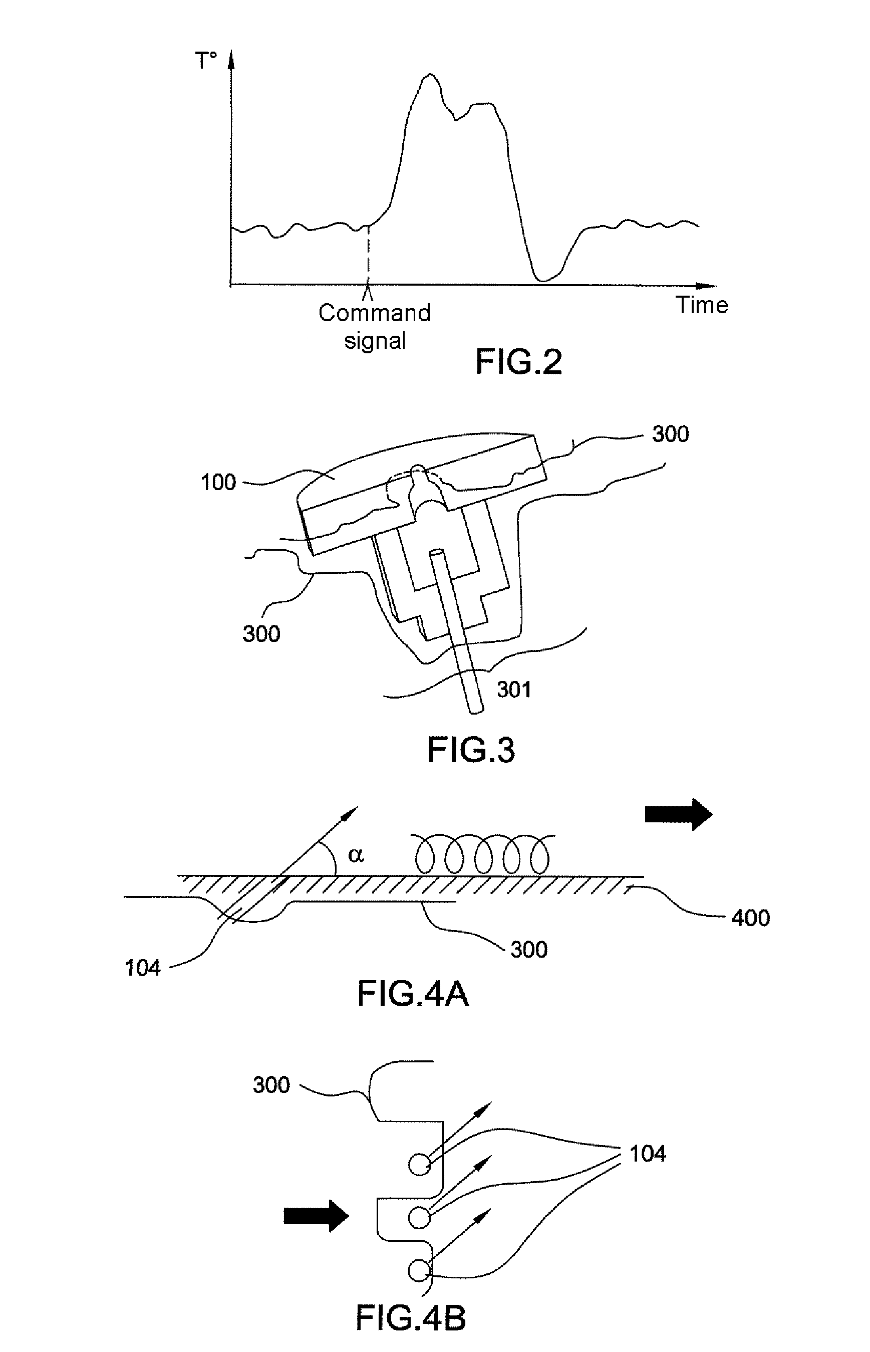
The present invention uses a signature that can be appreciated via the measurement of physical parameters that are characteristic of the operation of the monitored actuators.

Devices for detecting operating anomalies of a device, which use the detection of physical phenomena characteristic of the malfunction of the device, for example abnormal vibrations, are known in themselves. This monitoring is of a continuous nature.

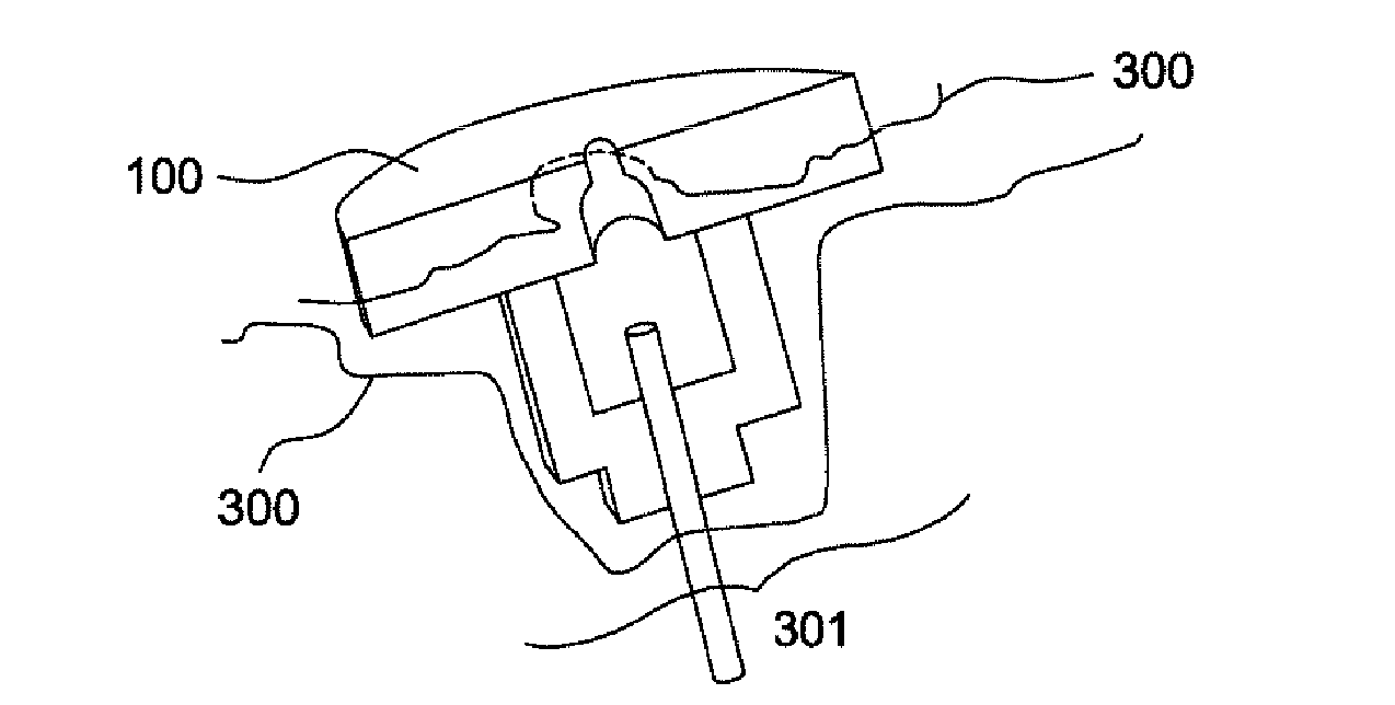
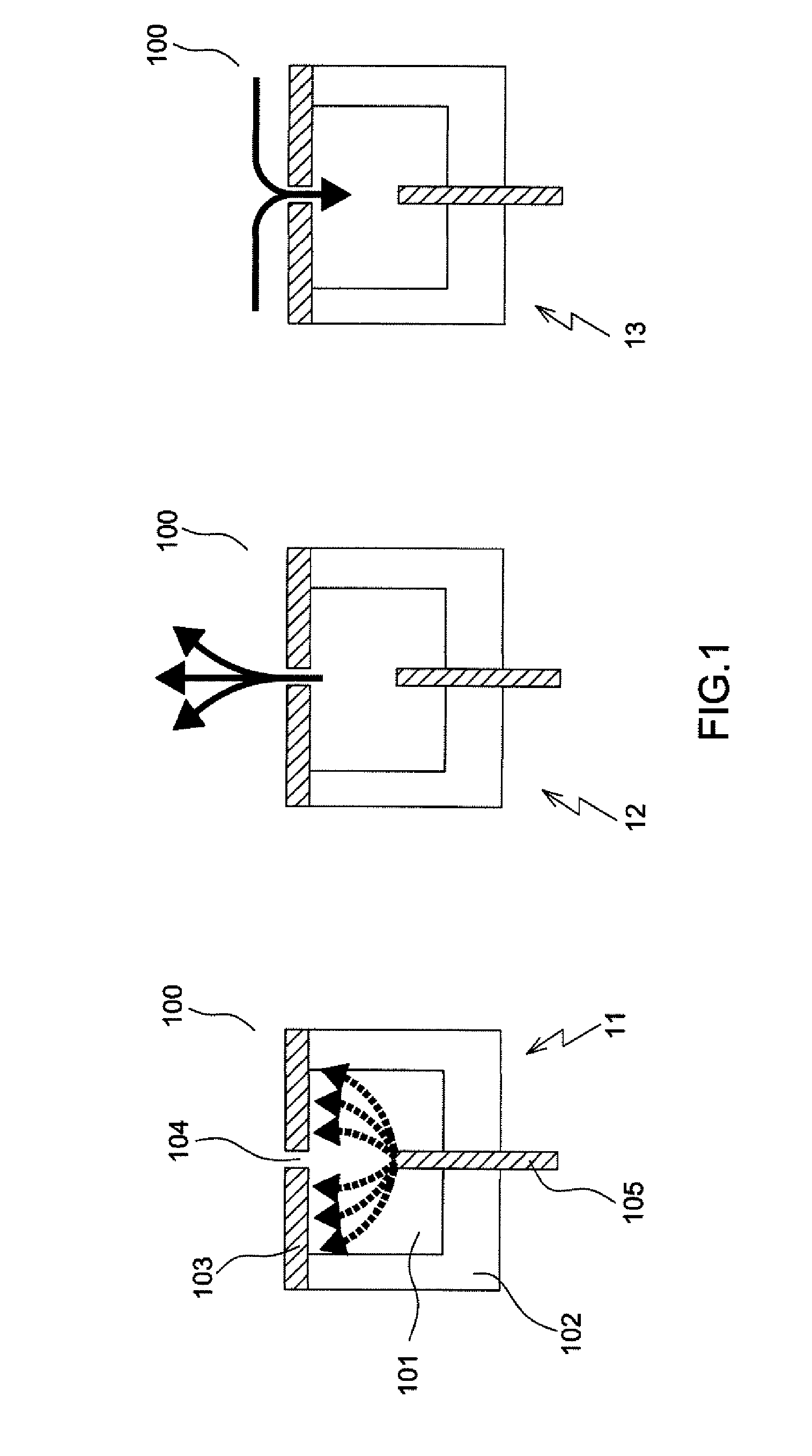
The device according to the invention uses a comparison of the expected physical consequence following the operation of the actuator with the physical consequence that is actually measured. “Physical consequence” is understood to be the change in physical parameters such as temperature or the characteristic vibration in the immediate vicinity of the actuator. This comparison is made each time the actuator is made to operate.

The device according to the invention uses a network of sensors making it possible to monitor a plurality of actuators independently of one anoth...


PUM


Abstract

A monitoring device for monitoring a plurality of microactuators includes an optical fibre with a plurality of sensors, each sensor being placed close to a microactuator and having optical properties varying as a function of at least one environmental parameter, the monitoring device also including a polling device with at least one transmitter/receiver for a fibre optic network, and processing means capable of modulating the frequency of the optical signal transmitted by the transmitter to select the sensor close to a given microactuator, and of comparing the received optical signal with a template characteristic of the correct operation of the microactuator, and of generating a resultant signal, representative of the correct operation of the monitored microactuator. The invention has applications in the field of health monitoring of vehicles, notably of aircraft.

Description

CROSS-REFERENCE TO RELATED APPLICATIONThis application claims priority to foreign French patent application No. FR 09 05509, filed on Nov. 17, 2009, the disclosure of which is incorporated by reference in its entirety.FIELD OF THE INVENTIONThe present invention relates to a device for monitoring the correct operation of a plurality of devices distributed in a structure, notably of actuators. It applies to the monitoring of the correct operation of items of equipment and of systems, notably applied in vehicles, and more particularly in aircraft.BACKGROUND OF THE INVENTIONThere are, notably in the transport field, an increasing number of onboard systems comprising a plurality of actuators distributed in a structure, sometimes in large numbers. The development of actuators of ever smaller dimensions allows a better integration of the latter and hence an increase in their number within a given system. In the aviation field, for example, it is desirable that an ever increasing number of ...

Claims


Application Information

Patent Timeline
IPC IPC(8): G01B11/16
CPCB64D43/00B64D2045/0085G01D5/268G01D5/35303B64C2230/18H04L12/403H04L2012/4028Y02T50/166G01M11/083Y02T50/10
Inventor GUICHARD, PHILIPPE
Owner THALES SA
Why Eureka
Try Eureka