Optical recording method, optical recording apparatus and optical storage medium

a recording method and optical recording technology, applied in the field of optical recording methods, optical recording apparatuses and optical storage media, can solve the problems of lowering the recording characteristics at initial recording, the proposed optical recording method and the optical storage medium cannot achieve sufficient overwrite characteristics, and the method cannot provide acceptable recording characteristics, etc., to achieve excellent overwrite characteristics and high linear-speed optical recording

Inactive Publication Date: 2008-05-20
VICTOR ADVANCED MEDIA CO LTD
View PDF6 Cites 8 Cited by
  • Summary
  • Abstract
  • Description
  • Claims
  • Application Information

AI Technical Summary

Benefits of technology

[0012]A purpose of the present invention is to provide an optical recording method, an optical recording apparatus and an optical storage medium that offer excellent overwrite characteristics in high linear-velocity (high×speed) optical recording to rewritable phase-change optical storage media, such as, optical disks and optical cards.
[0013]Another purpose of the present invention is to provide an optical recording method, an optical recording apparatus and an optical storage medium that offer excellent overwrite characteristics in optical recording at any linear velocity selected among a plurality of linear velocities over a range from low linear velocity (low×speed) to high linear velocity (high×speed).

Problems solved by technology

However, the inventors of the present invention found that the proposed optical recording method and optical storage medium cannot achieve sufficient overwrite characteristics (particularly characteristics at initial overwriting) at high linear velocity (for example, DVD×4 speed or higher).
However, this method increases the erasing power Peh in high linear-velocity recording, which makes sections to be crystalline amorphous, thus lowering recording characteristics at initial recording.
The inventors of the present invention, however, found this method cannot provide acceptable recording characteristics over a wide range (from low to high) of linear velocity, each linear velocity having its own optimum erasing-power level.
The inventors of the present invention, however, found this method cannot provide acceptable overwrite characteristics for several times of overwriting because of low erasing power at low linear velocity.
As discussed above, the conventional optical recording methods with lower reflectivity of un-recorded sections than that of the sections after recorded or erased and the conventional optical storage media that exhibit low reflectivity on un-recorded sections after initialized cannot provide sufficient jitter characteristics after overwriting in high linear-velocity recording, thus having difficultly in providing acceptable overwrite characteristics.
These methods, however, cannot offer sufficient initial recording characteristics or overwrite characteristics because of large erasing power Peh at high linear velocity or cannot offer sufficient overwrite characteristics because of small erasing power Pel at low linear velocity.

Method used


Image

  • Optical recording method, optical recording apparatus and optical storage medium
  • Optical recording method, optical recording apparatus and optical storage medium
  • Optical recording method, optical recording apparatus and optical storage medium

Examples


embodiment sample a-1

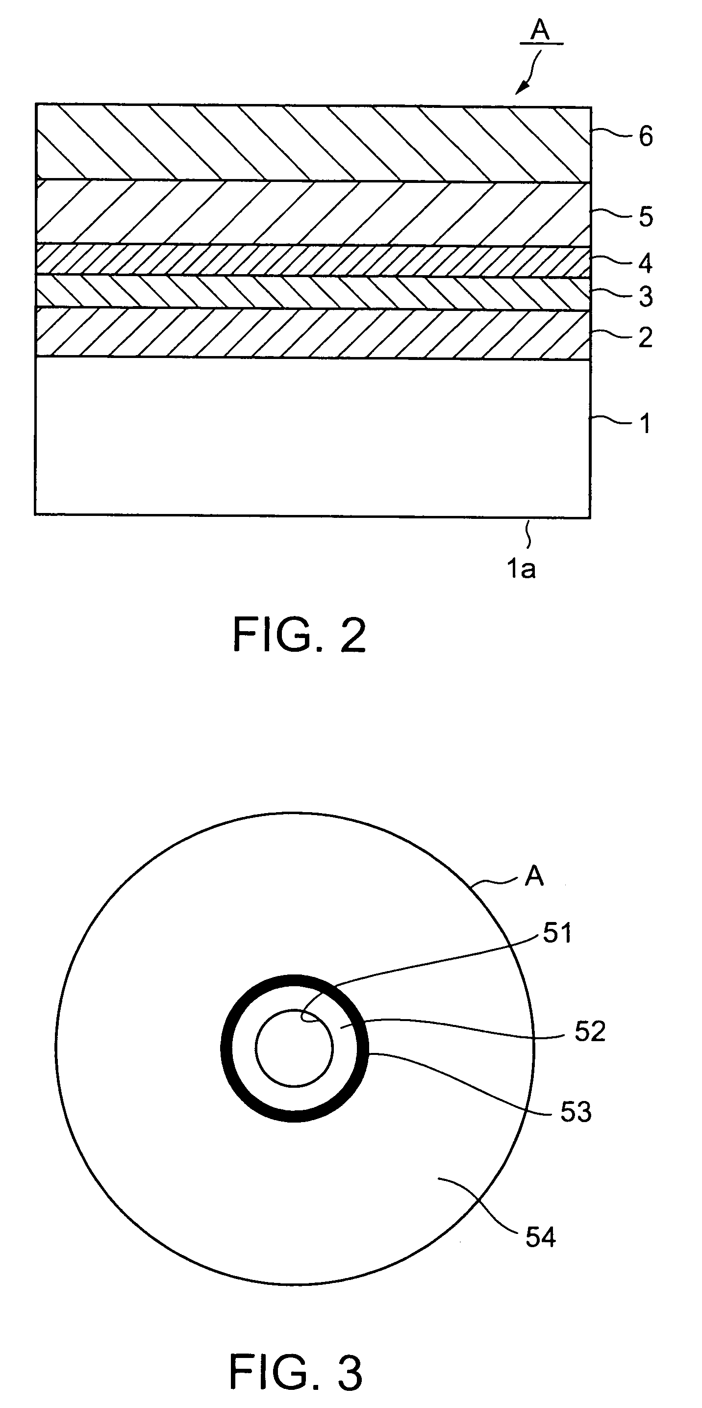
[0105]Several layers which will be disclosed later, were formed on a on a substrate 1 made of a polycarbonate resin with 120 mm in diameter and 0.6 mm in thickness. Grooves were formed on the substrate 1 at 0. 74 μm in track pitch, with 25 nm in groove depth and about 40:60 in width ratio of groove to land. The grooves stuck out when viewed from an incident direction of a laser beam in recording, reproduction or erasure.

[0106]After a vacuum chamber was exhausted up to 3×10⁻⁴ Pa, a 70 nm-thick first protective layer 2 was formed on the substrate 1 by high-frequency magnetron sputtering with a target of ZnS added with 20-mol % SiO2 at 2×10⁻¹ Pa in Ar-gas atmosphere.

[0107]Formed on the first protective layer 2, in order, were a 16 nm-thick recording layer 3 with a target of an alloy of 4 elements Ge—In—Sb—Te, a 16 nm-thick second protective layer 4 of the same material as the first protective layer 2, and a 120 nm-thick reflective layer 5 with a target of Ag—Pd—Cu.

[0108]The substrate 1...

embodiment sample a-2

[0116]The optical storage medium A in the embodiment sample A-2 was identical to that of the embodiment sample A-1. Recording was conducted and evaluated with the same recording requirements except change in erasing power Pe to 3.8 [mW]. Results were 17.4 in R0, and 17.5 in R1 after irradiated once with a laser beam having the erasing power Pe=3.8 [mW] (R1 / R0=1.006).

[0117]Initial characteristics and overwrite recording characteristics were as shown in FIG. 17: 6.8% in DOW-0 jitter, 8.6% in DOW-1 jitter, and 7.9% in DOW-9 jitter. Moreover, although not shown, DOW-10000 jitter was 9.2%. Thus, the embodiment sample A-2 was always stable in characteristics after overwriting, with excellent recording characteristics, like the embodiment sample A-1.

embodiment sample a-3

[0118]The optical storage medium A in the embodiment sample A-3 was identical to that of the embodiment sample A-1. Recording was conducted and evaluated with the same recording requirements except change in erasing power Pe to 5.6 [mW]. Results were 17.4 in R0, and 17.9 in R1 after irradiated once with a laser beam having the erasing power Pe=5.6 [mW] (R1 / R0=1.029).

[0119]Initial characteristics and overwrite recording characteristics were as shown in FIG. 17: 7.0% in DOW-0 jitter, 8.7% in DOW-1 jitter, and 8.4% in DOW-9 jitter. Moreover, although not shown, DOW-10000 jitter was 9.5%. Thus, the embodiment sample A-3 was always stable in characteristics after overwriting, with excellent recording characteristics, like the embodiment sample A-1.

Comparative Sample A-4

[0120]The optical storage medium A in the comparative sample A-4 was identical to that of the embodiment sample A-1. Recording was conducted and evaluated with the same recording requirements except change in erasing power...


PUM

PropertyMeasurementUnit
thicknessaaaaaaaaaa
thicknessaaaaaaaaaa
thicknessaaaaaaaaaa

Abstract

Information to be recorded is recorded in a recording layer of a phase-change optical storage medium. The information to be recorded is modulated to generate modulated data. Desired mark-length data is generated based on the modulated data. Generated further based on the mark-length data is a recording pulse pattern of recording pulses rising from an erasing power and formed between a recording power larger than the erasing power and a bottom power smaller than the erasing power and of erasing pulses rising from the bottom power to the erasing power. A recording light beam is then irradiated onto the recording layer in accordance with the recording pulse pattern to record at least one recorded mark representing the information to be recorded. Used in recording is an optimum erasing power, as the erasing power, the optimum erasing power satisfying an expression (1): 1.000<(R1 / R0)<1.030 . . . (1) in which R0 is a reflectivity exhibited by an un-recorded section of the recording layer, on which no data has ever been recorded, when irradiated with a reproducing light beam, and R1 is a reflectivity exhibited by the un-recorded section when irradiated with the reproducing light beam after irradiated once with a beam having the erasing power.

Description

CROSS-REFERENCE TO RELATED APPLICATIONS[0001]This application is based on and claims the benefit of priority from the prior Japanese Patent Application No. 2004-023430 filed on Jan. 30, 2004 and Japanese Patent Application No. 2004-023431 filed on Jan. 30, 2004, the entire contents of which are incorporated herein by reference.BACKGROUND OF THE INVENTION[0002]The present invention relates to an optical recording method, an optical recording apparatus and an optical storage medium, in or from such a storage medium, data being recorded, erased or reproduced with irradiation of a light beam (for example, a laser beam).[0003]Phase-change optical storage media are data-rewritable storage media, such as, recent CD-RW, DVD-RW and DVD-RAM. Especially, DVD-RW and DVD-RAM are used for recording and rewriting a large amount of data, such as video data. Phase-change optical storage media require excellent overwrite characteristics as well as recording characteristics.[0004]Structures of and rec...

Claims


Application Information

Patent Timeline
Patent Type & Authority Patents(United States)
IPC IPC(8): G11B7/00G11B7/0045G11B7/005G11B7/0055G11B7/006G11B7/125
CPCG11B7/1267G11B7/0062
Inventor TABATA, HIROSHIMATSUMOTO, IKUOTOKUI, KENJIYONEHARA, KAZUOSHIMOMAI, KENICHI
Owner VICTOR ADVANCED MEDIA CO LTD
Why Eureka
Try Eureka