Fixing device with peeling member for an image forming apparatus

a fixing device and image forming technology, applied in the field of fixing devices, can solve the problems of deteriorating fixing performance, structurally difficult to feed such a calorie instantaneously, and insufficient fixing treatment, and achieve the effects of stable peeled, high fixing performance and high quality

Active Publication Date: 2008-12-09
FUJIFILM BUSINESS INNOVATION CORP
View PDF4 Cites 6 Cited by
  • Summary
  • Abstract
  • Description
  • Claims
  • Application Information

AI Technical Summary

Benefits of technology

[0018]The present invention also provides a fixing device capable of keeping a high fixing performance even in the case of speeding up a process of an image forming apparatus including the fixing device.
[0024]According to the fixing device and the image forming apparatus, even in the case of speeding up the image forming apparatus, the recording paper sheet can be stably peeled off from the belt member. Moreover, the high fixing performance can be kept to provide many images of a high quality for a short time period.

Problems solved by technology

However, the two-roll type fixing device of the related art has a problem that a sufficient fixing treatment is difficult for a number of sheets of recording paper being continuously sent at a high speed.
As a result, the two-roll type fixing device has found it structurally difficult to feed such a calorie instantly and sufficiently from the heater arranged in the fixing roll as corresponds to the calorie to be rubbed by the recording paper sheets from the surface of the fixing roll.
As a result, if the two-roll type fixing device is continuously fed at the high speed with the recording paper sheets, the surface temperature of the fixing roll gradually lowers to cause a disadvantage that the fixing performance is gradually deteriorated.
Especially in case thick sheets of paper or the like of a high heat capacity are employed as the recording paper sheets, the calorie to be rubbed from the surface of the fixing roll increases to lower the fixing performance and to enlarge the temperature droop with the result that the image quality is deteriorated by the fixing failure.
Especially in case the image forming apparatus is speeded up, when a peeling failure once occurs in the fixing device to cause a paper clogging (or a jamming), many succeeding paper sheets are damaged by the influence of the jamming.
If the peeling pawl is used for the peeling action, the fixing belt surface is easily abraded by the peeling pawl.
When the abrasion by the peeling pawl occurs on the fixing belt surface, a fixing irregularity corresponding to the abrasion mark in the surface of the fixing belt may be caused on the fixed image thereby to degrade the image quality.
As the abrasion of the surface of the fixing belt proceeds, moreover, the fixing belt of the thin layer may be finally broken to damage the function of the fixing device.
In case these air gaps occur, the air bubbles may migrate to disturb the unfixed toner, if the toner on the paper sheet in the nip portion is not completely fixed yet.
As a result, the image failure such as the irregularity occurs in the fixed image thereby to cause a serious problem that the degradation of the image quality is invited.

Method used


Image

  • Fixing device with peeling member for an image forming apparatus
  • Fixing device with peeling member for an image forming apparatus
  • Fixing device with peeling member for an image forming apparatus

Examples


first embodiment

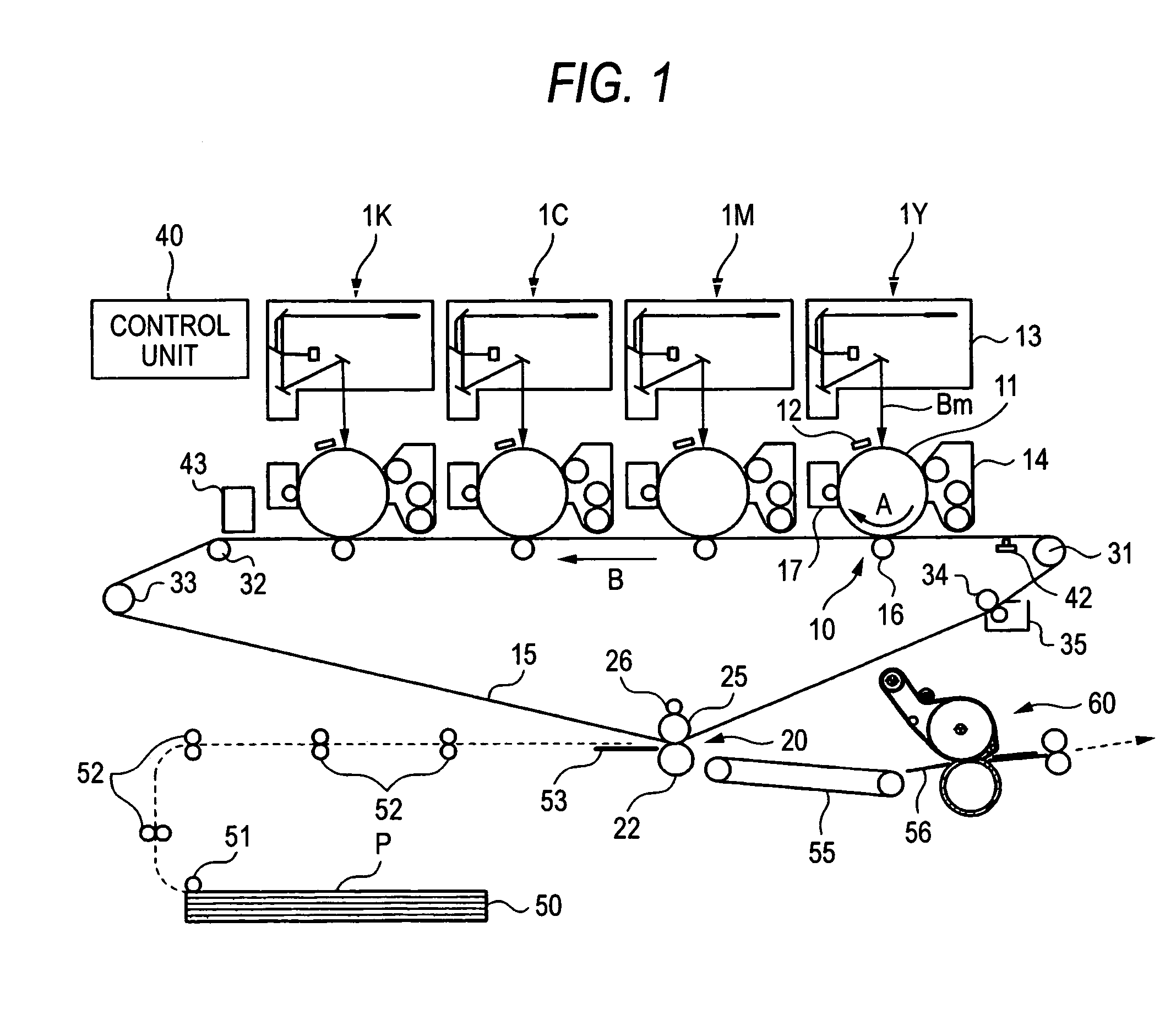
[0039]FIG. 1 is a schematic configuration diagram showing an image forming apparatus according to an exemplary embodiment of the present invention. The image forming apparatus shown in FIG. 1 is an intermediate transfer type image forming apparatus, which is generally called the “tandem type”. This image forming apparatus is provided with: plural image forming units 1Y, 1M, 1C and 1K for forming toner images of individual color components by the electronic photography; a primary transfer unit 10 for transferring the individual color component toner images formed by the individual image forming units 1Y, 1M, 1C and 1K, sequentially (or primarily) to an intermediate transfer belt 15; a secondary transfer unit 20 for transferring the superposed toner image transferred to the intermediate transfer belt 15, generally (or secondarily) to a paper sheet P or a recording medium (or a recording paper sheet); and a fixing device 60 for fixing the secondarily transferred image to the paper shee...

second embodiment

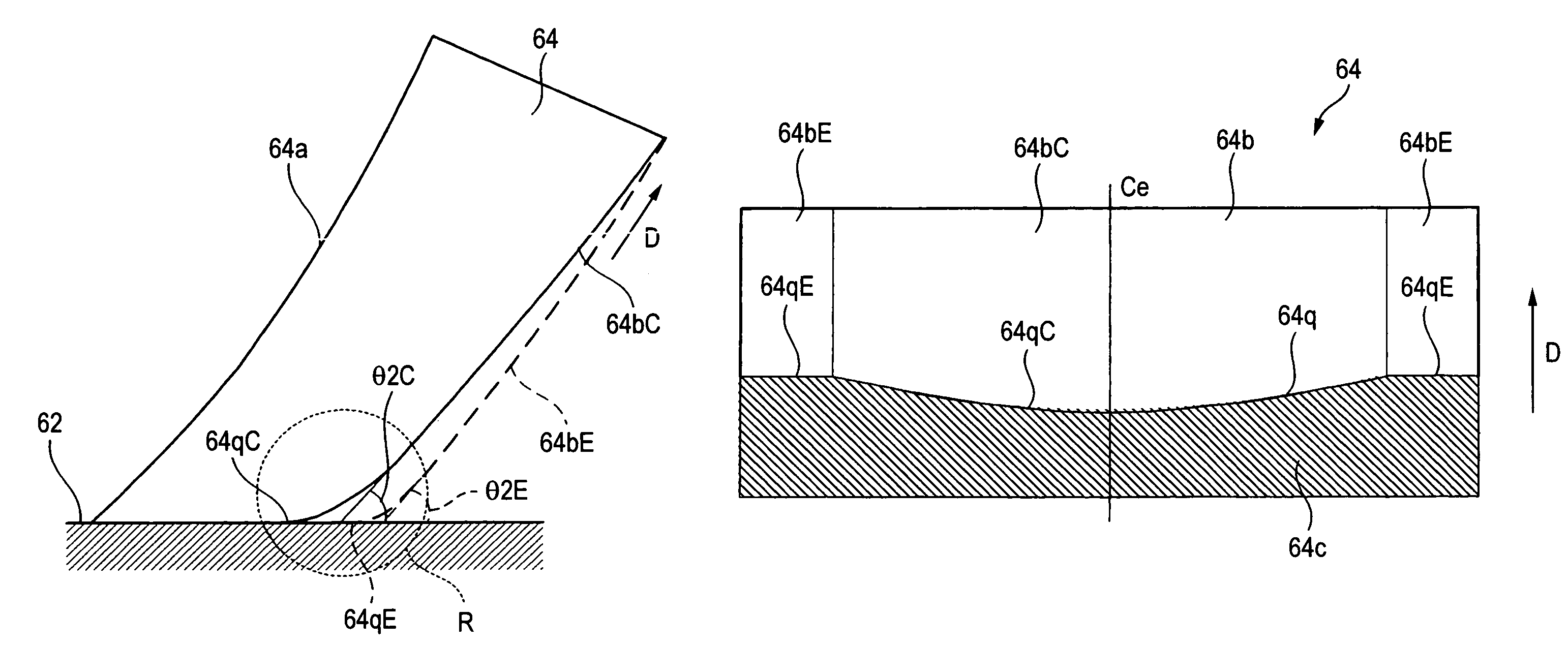
[0137]The first exemplary embodiment has been described on the configuration, in which the paper sheet P is sequentially peeled off, from the widthwise middle portion to the two end portions, by forming the outer side face 64b of the peeling pad 64 so that the central portion spacing edge 64qC may be positioned more upstream in the moving direction of the fixing belt 610 than the end portion leaving edges 64qE. A second exemplary embodiment is described on the configuration, in which the paper sheet P is sequentially peeled by making the inclination angle θ2C of the outer side face 26bC of the longitudinal middle portion more than the inclination angle θ2E of the outer side faces 64bE of the two end portions. Here, structures similar to those of the first embodiment are designated by similar reference numerals, and their detailed descriptions are omitted.

[0138]FIGS. 9A and 9B presents diagrams for explaining the shape of the peeling pad 64, and FIG. 9A presents a cross sectional dia...

third embodiment

[0146]The first embodiment has been described on the configuration, in which the pressure roll 62 is used as the pressure member arranged and pressed to contact with the fixing belt module 61 in the fixing device 60 to be mounted in the image forming apparatus. A third exemplary embodiment is described on the configuration using a pressure belt module 70, in which a pressure belt 700 is stretched by plural rolls acting as the pressure member. Here, structures similar to those of the first embodiment are designated by similar reference numerals, and their detailed descriptions are omitted.

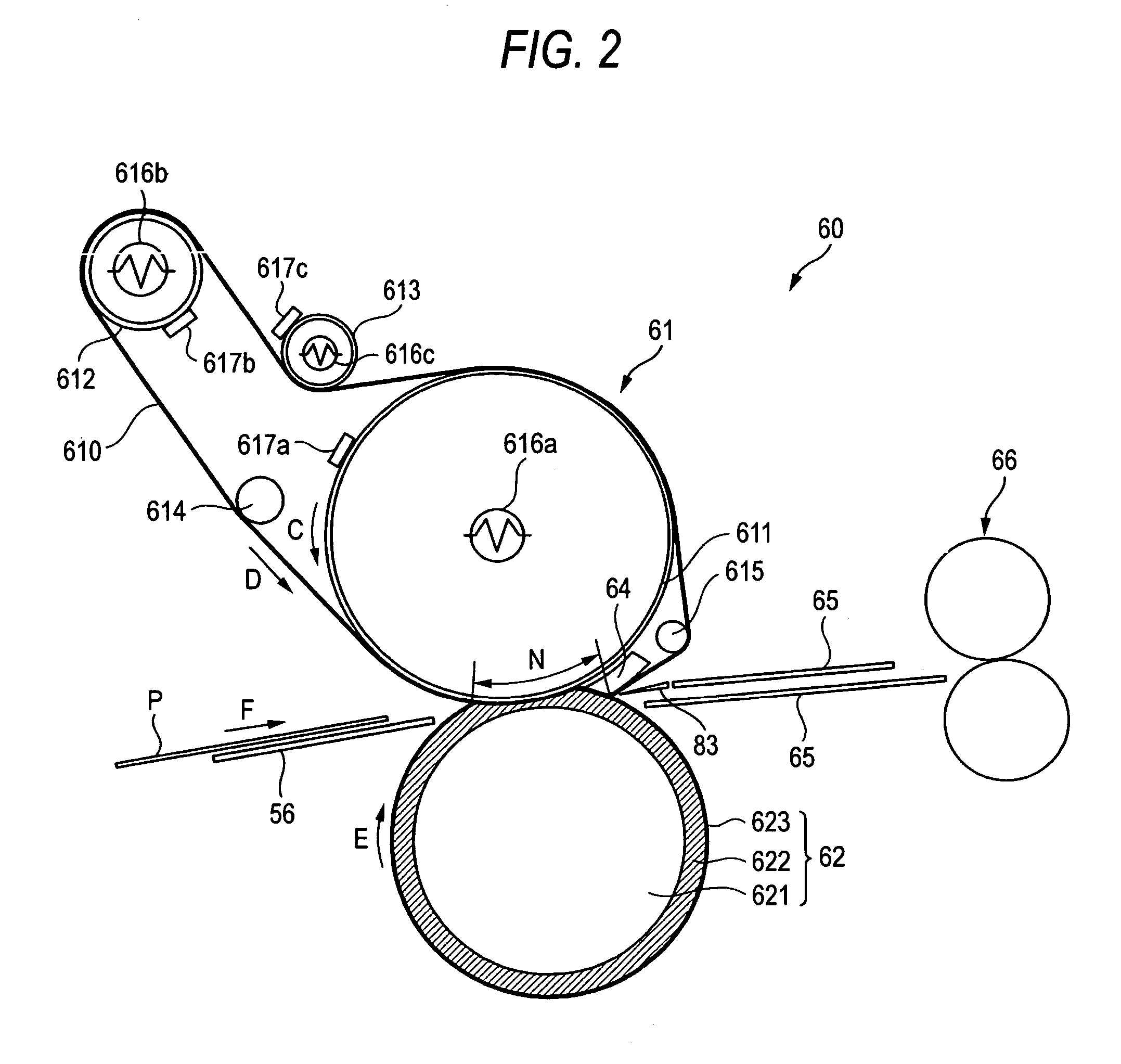
[0147]FIG. 11 is a side cross section showing the configuration of a fixing device 90 according to this embodiment. The structure of the fixing device 90 of this embodiment is similar to that of the fixing device 60 of the first embodiment, excepting that the pressure belt module 70 is arranged as the pressure member in place of the pressure roll 62.

[0148]The pressure belt module 70 of this embodime...


PUM


Abstract

A fixing device for fixing a toner image on a recording material, includes a rotatable endless belt member, a pressure member provided to press into contact and form a nip portion with the belt member, through which the recording material passes, and a peeling member provided downstream of the nip portion, peeling the recording material passed through the nip portion from the belt member by bending the belt member to have different shapes at a widthwise middle portion and at both end portions while the belt member is passing through the peeling member.

Description

CROSS-REFERENCE TO RELATED APPLICATIONS[0001]This application is based upon and claims the benefit of priority from the prior Japanese Patent Applications No. 2005-248180, filed on Aug. 29, 2005, the entire contents of which are incorporated herein by reference.BACKGROUND OF THE INVENTION[0002]1. Field of the Invention[0003]The present invention relates to a fixing device or the like to be used in an image forming apparatus utilizing the electronic photography and, more particularly, to a fixing device or the like equipped with a turnable belt member.[0004]2. Description of the Related Art[0005]In the image forming apparatus such as a copier or a printer using the electronic photography, the image formation is performed, as follows. First of all, the surface of a photosensitive element (or a photosensitive drum) formed in a drum shape, for example, is homogeneously charged by a charging device. The photosensitive drum charged is scanned with and exposed to a beam controlled on the b...

Claims


Application Information

Patent Timeline
Patent Type & Authority Patents(United States)
IPC IPC(8): G03G15/20
CPCG03G15/2028G03G2215/2016G03G2215/2022
Inventor BABA, MOTOFUMIUEHARA, YASUHIRO
Owner FUJIFILM BUSINESS INNOVATION CORP
Why Eureka
Try Eureka