Electrical power metering system

a technology of electrical power metering and power consumption, applied in the integration of power network operation system, electric devices, instruments, etc., can solve the problems of increasing the cost of electric utility bills, inaccurately reflecting power consumption, and current electrical power meters not providing the ability to identify locations in buildings

Inactive Publication Date: 2008-12-09
HUDSON BAY WIRELESS
View PDF39 Cites 86 Cited by
  • Summary
  • Abstract
  • Description
  • Claims
  • Application Information

AI Technical Summary

Benefits of technology

[0010]The present invention relates to a wireless electrical power metering system. The invention comprises a computer or processor connected to a power line meter, a multichannel power line transceiver, and a wireless interface. The power line meter measures power consumption information, and the processor converts same for transmission as standard Internet Protocol (IP) traffic across a network. The processor can be connected to a household local area network (LAN), a wireless area network, a power line data network, or the Internet. Power consumption information can be measured and transmitted to a wireless monitoring station, one or more computers within the household, or directly to a utility company via the Internet. Appliances located in the dwelling can be selectively controlled by the processor to maximize energy savings.
[0013]The present invention further provides an electrical power metering system having Global Positioning System (GPS), emergency alert reception, biometric scanning, and environmental monitoring capabilities. A GPS receiver allows for the precise location of the electrical power metering system to be determined, stored in memory, and transmitted to a remote location (e.g., to a power utility). An emergency alert receiver allows for the receiption of emergency signals from a central agency (e.g., Emergency Alert System (EAS) signals), and local alerts can be generated within a dwelling. A biometric scanner (e.g., thumbprint or retinal scanner) permits only authorized users to access the electrical power metering system. One or more environmental sensors (e.g., temperature, humidity, etc.) in communication with the electrical power metering system allow for the measurement of local environmental conditions, particularly in harsh or remote environments. The system also allows for monitoring of power consumption in mobile environments, such as in automobiles.

Problems solved by technology

Further, increased electrical power consumption also results in an increase in the cost of electric utility bills.
Frequently, a single power utility meter, whether analog or digital, services a multifamily dwelling and does not accurately reflect power consumption by individual families or occupants of the dwelling.
Inaccuracies in billing can result, as many families split the total utility bill for the dwelling evenly and without regard to actual power consumption by each occupant.
In addition to these shortcomings, current electrical power meters do not provide the ability to identify locations in the building where power is most frequently consumed and / or wasted.
Such systems, however, require the installation of numerous components at the dwelling.
Further, these systems often require the presence of an RF back-haul station or base unit, and do not allow for the direct connection of the meter to the Internet via a wired or wireless network connection.
Moreover, there has yet to be developed a wireless power metering system that allows for the transmission of power consumption data, in addition to standard network data, over one or more power lines within a dwelling.

Method used


Image

  • Electrical power metering system
  • Electrical power metering system
  • Electrical power metering system

Examples


Embodiment Construction

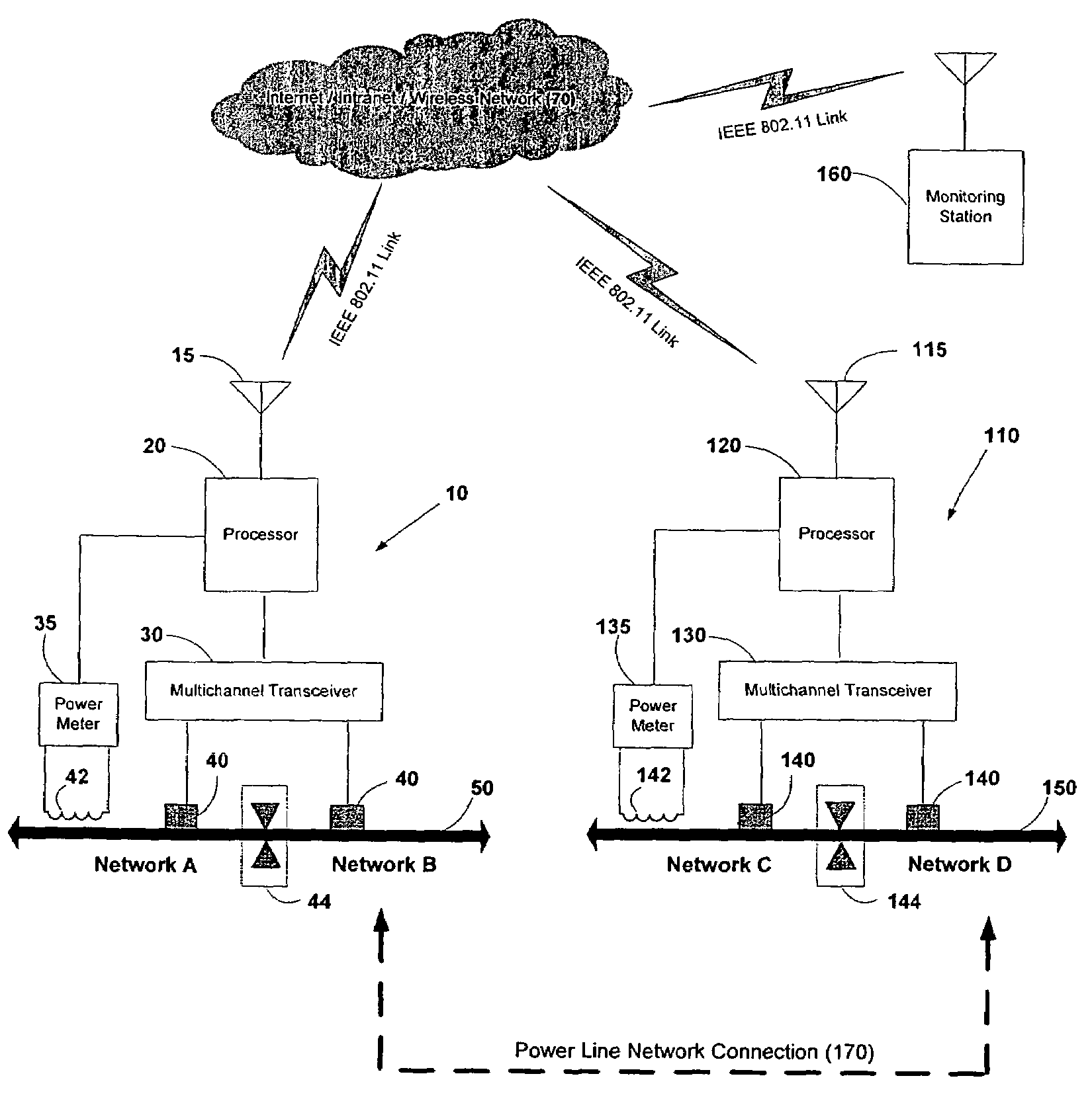
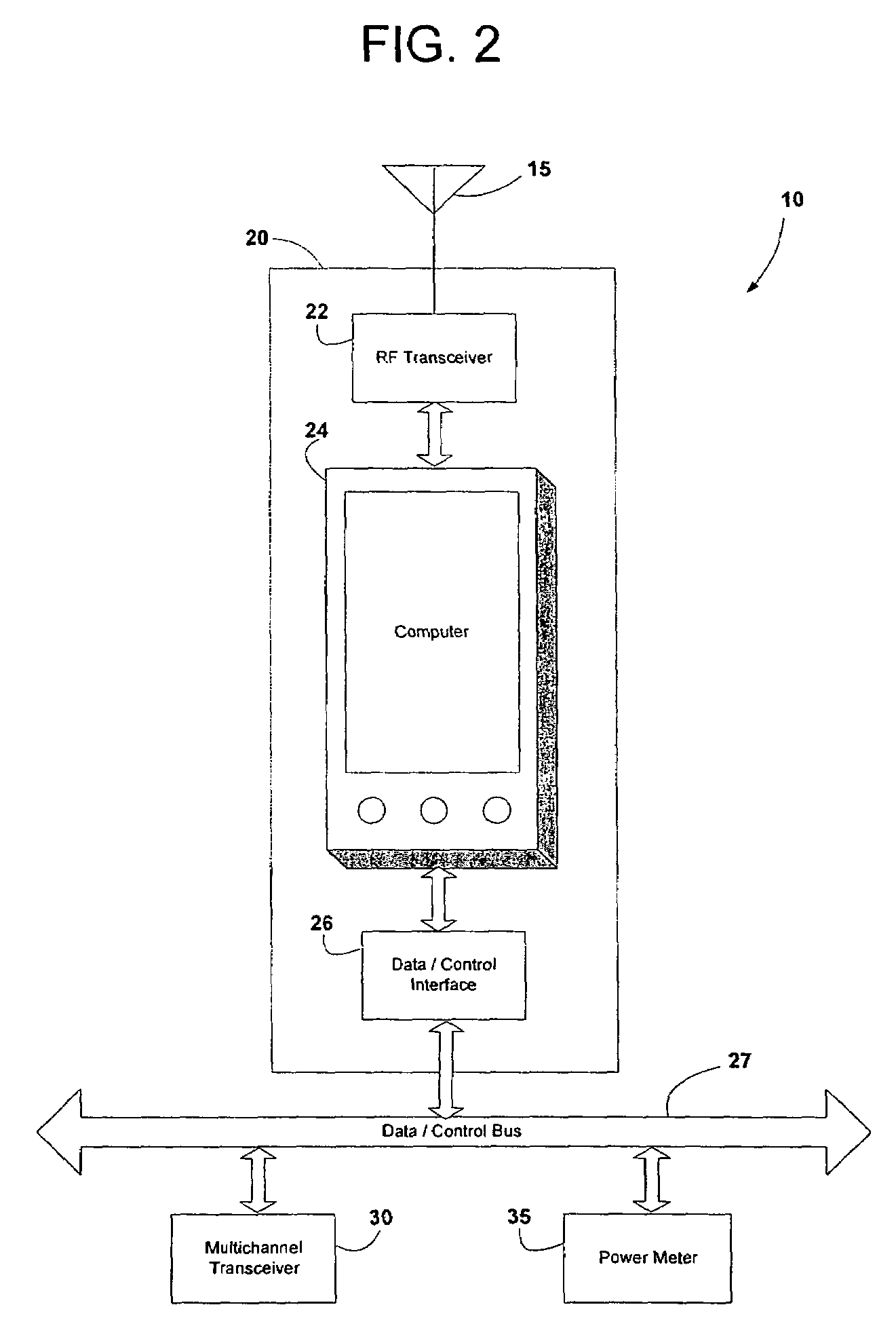
[0025]The present invention relates to a wireless electrical power metering system. A computer, connected to a wireless transceiver, a multichannel power line transceiver, and a power meter that measures power consumption data from the power line, converts the measured data to IP format for transmission across a wired or wireless network. The present invention can also remotely control appliances in response to power consumption trends, and provides network connectivity and firewall capabilities between an existing network within a dwelling and a power line network. A wireless monitoring station allows power consumption data to be remotely monitored.

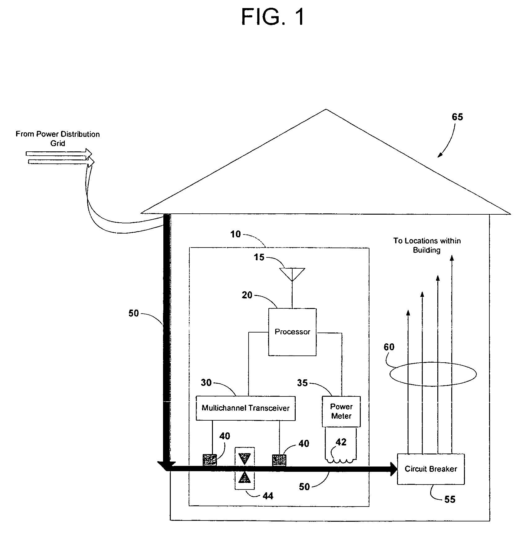
[0026]FIG. 1 is a schematic diagram showing the wireless power metering system of the present invention, indicated generally at 10 and installed in a dwelling 65. A power line 50 connects the dwelling 65 to the local power distribution grid. The power line 50 can be any power line known in the art, such as a single phase, two-phase, or t...


PUM


Abstract

A wireless electrical power metering system is provided. A processor having a multichannel power line transceiver, a wireless transceiver, and a power meter attached thereto measures power consumption information at a location. The processor converts the power consumption information into IP-based data, and transmits same over the wireless transceiver. The information can be wirelessly received by a remote monitoring station or transmitted across the Internet for storage, analysis, and billing. The processor can remotely control appliances in response to power consumption trends. The processor can relay information between a wired or wireless network and a power line network, to allow multiple dwellings to be networked using power lines, and households to be connected to the Internet via a power line network. The electrical power metering system also includes Global Positioning System (GPS), biometric scanning, emergency alert reception, and environmental monitoring capabilities.

Description

RELATED APPLICATIONS[0001]This application is a continuation-in-part of U.S. patent application Ser. No. 10 / 280,533 filed Oct. 25, 2002, now U.S. Pat. No. 7,058,524, the entire disclosure of which is expressly incorporated herein by reference.BACKGROUND OF THE INVENTION[0002]1. Field of the Invention[0003]The present invention relates to power consumption measurement, and more specifically, to an electrical power metering system for measuring electrical power consumption, converting the measurements to IP format, and delivering the information in one or more wired or wireless networks.[0004]2. Related Art[0005]In today's society, electrical power is being consumed at an increasing rate. As individuals continue to purchase electronic equipment, such as stereos, televisions, DVD players, personal computers, appliances, air conditioners, and other similar devices, the demand for electrical power increases. Further, increased electrical power consumption also results in an increase in t...

Claims


Application Information

Patent Timeline
Patent Type & Authority Patents(United States)
IPC IPC(8): G06F19/00G01R21/00G01R21/06H02J13/00H04L29/06
CPCG01D4/002G01D4/004G01R22/063H04L69/161Y02B90/242Y04S20/322H04L69/16Y02B70/3266Y02B90/241Y02B90/246Y04S20/242Y04S20/32Y04S20/42Y02B70/30Y02B90/20Y04S20/30
Inventor HAYES, PAUL V
Owner HUDSON BAY WIRELESS
Why Eureka
Try Eureka