-48v DC frequency conversion speed regulation temperature control system

A temperature control system and DC frequency conversion technology, applied in heating and ventilation control systems, heating and ventilation safety systems, household heating, etc., can solve problems such as battery swelling, temperature rise in temperature control cabinets, and system failure. Achieve the effect of small energy consumption and prolong service life

Active Publication Date: 2011-12-14
深圳易通技术股份有限公司
View PDF9 Cites 3 Cited by
  • Summary
  • Abstract
  • Description
  • Claims
  • Application Information

AI Technical Summary

Problems solved by technology

The disadvantage of this solution is that the cold source cannot be output in the first case of power failure, and the second is that the output cutoff of the cold source must be realized by powering off the compressor, which affects the service life of the compressor
The AC constant power mode is adopted, and the cold source cannot be output during a power failure, resulting in an increase in the temperature inside the temperature control cabinet. In severe cases, the battery will swell to failure, and the base station cannot provide services at this time
Another important disadvantage is the use of constant power output cooling capacity, which cannot provide sufficient actual cooling capacity, and always maximizes power output
Unfavorable energy saving
When the temperature meets or does not meet the setting, it is necessary to frequently switch the compressor to work or stop, which will affect the service life of the compressor
[0004] At present, the temperature control of cabinets mostly uses AC compressors to realize cooling control. This method has the following disadvantages: 1. The system cannot work when the power is off.
2. The current cooling capacity output is a fixed mode
3. Cut off the cold source by cutting off the power of the compressor, which will affect the life of the product
4. The air volume output is also constant, and the output cannot be modulated according to the target temperature and ambient temperature

Method used


Image

  • -48v DC frequency conversion speed regulation temperature control system
  • -48v DC frequency conversion speed regulation temperature control system
  • -48v DC frequency conversion speed regulation temperature control system

Examples


Embodiment Construction

[0021] The present invention will be further described below with reference to the accompanying drawings and embodiments.

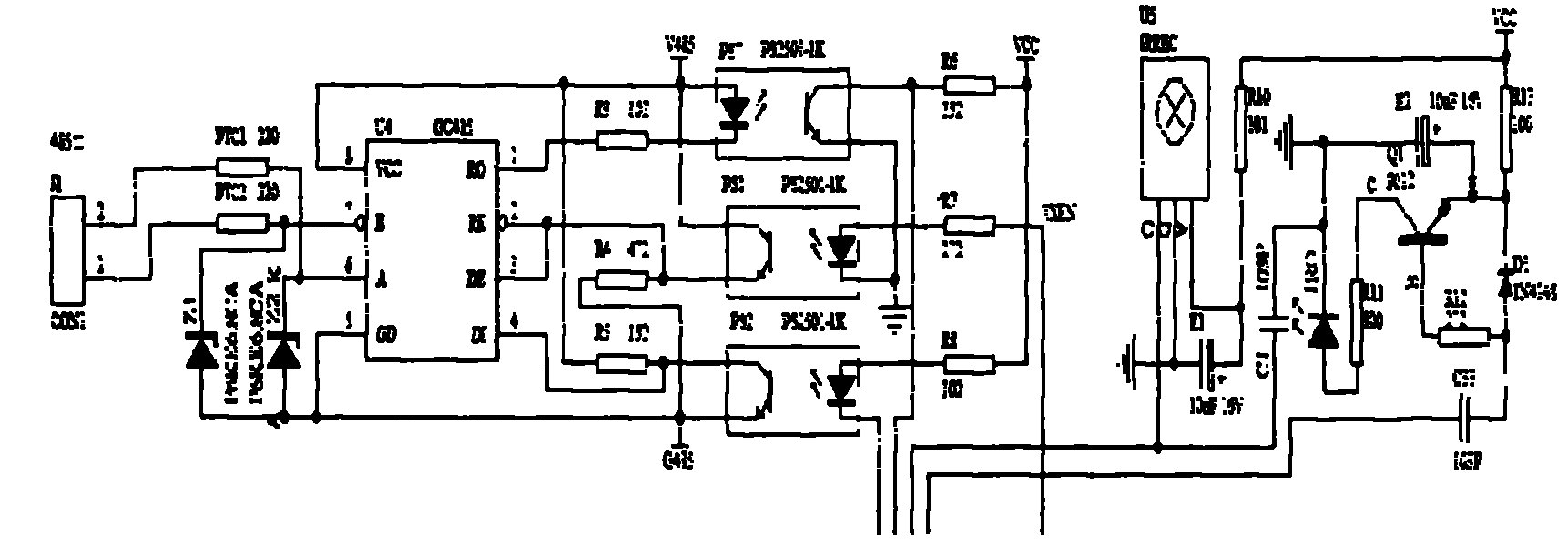
[0022] figure 1 It is the communication unit between the control system and the external or monitoring center, and J1 is the RS485 communication output. The whole is equipped with an isolation circuit, which is completely isolated from the power system of the target unit, and can achieve high anti-interference and high stability.

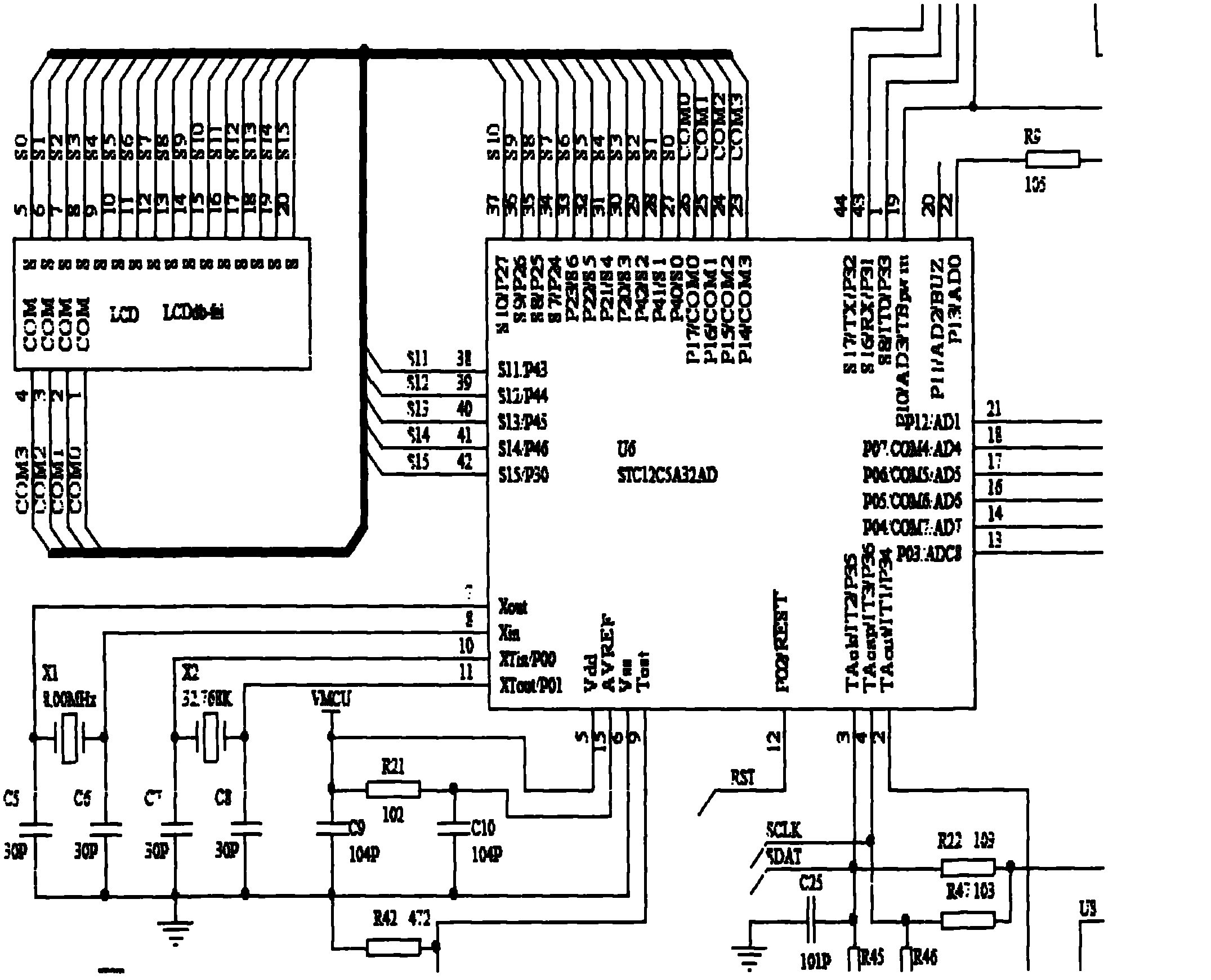
[0023] figure 2 It is the main control CPU and LCD display unit, and is the control core and command output center of the whole machine. Liquid crystal LCD displays real-time data, including target unit temperature and humidity, compressor speed and fan speed display. Can visually see the corresponding relationship between temperature and speed. And it can display the running time and power consumption statistics of the system in real time.

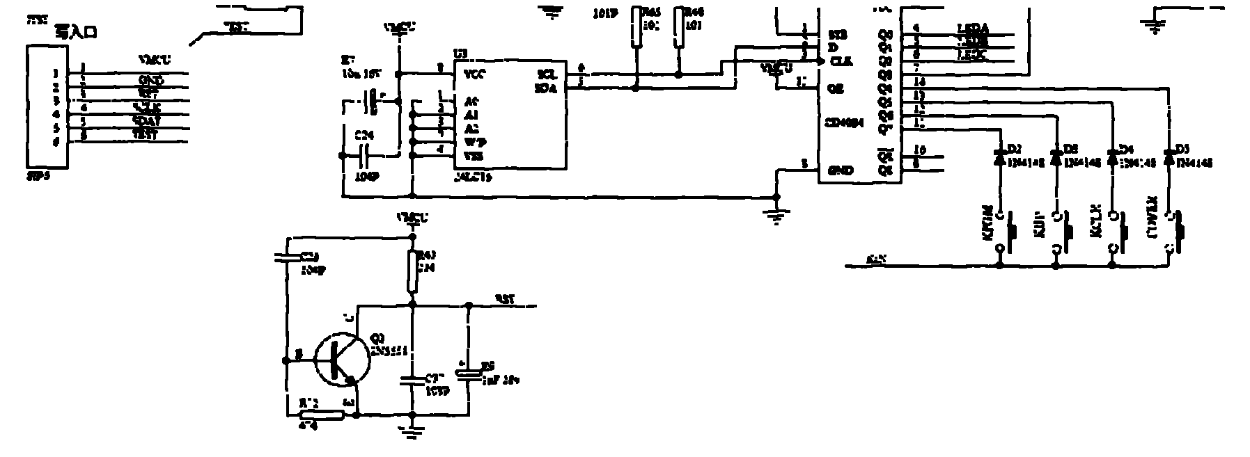
[0024] image 3 Input for online software upgrade and man-machine dialogue. Co...


PUM


Abstract

The invention relates to a direct current frequency-conversion speed-regulation temperature control system which comprises a power supply system, a PWM (pulse width modulation) fan, a variable speed fan and an AO (analogue output) drive compressor. The system is characterized in that the power supply system provides minus 48V direct current; the rotation speed of the PWM fan is adjustable so as to achieve adjustable wind speed; and the compressor is a variable speed compressor, and a flexible start mode is adopted. The temperature control method of the direct current frequency-conversion speed-regulation temperature control system of the claim 1 is utilized, the cold or heat output of the refrigerating and heating unit is mainly controlled through target unit temperature curve changes; the method for controlling the cold and heat is provided according to requirements, and the temperature requirement of the target unit can be met with less energy resource consumption; and the energy conservation maximization is realized.

Description

technical field [0001] The invention relates to a refrigeration system, and further relates to a temperature control system of a cabinet. Background technique [0002] At present, China Mobile, China Telecom, and China Unicom, the three major operators, consume too much power. Energy saving and emission reduction are very urgent. In order to minimize the running time of the air conditioner in the base station of the computer room, it is necessary to place the spare battery in a relatively constant temperature environment. The current battery temperature control system all adopts AC power supply system. The disadvantage of this solution is that the cooling source cannot be output in the first case of a power failure, and the second is that the output cutoff of the cold source must be realized by cutting off the power of the compressor, which affects the service life of the compressor. [0003] Today, when my country's energy resources are becoming increasingly tense, power o...

Claims


Application Information

Patent Timeline
Patent Type & Authority Applications(China)
IPC IPC(8): F24F11/00
Inventor 李明伟
Owner 深圳易通技术股份有限公司
Why Eureka
Try Eureka