System and method for recovering regenerative power in a vehicle, and vehicle using the same

a regenerative power and vehicle technology, applied in the field of system and method for recovering regenerative power in a vehicle, can solve the problem that the electric machine is only capable of recovering kinetic energy

Active Publication Date: 2008-12-16
FORD GLOBAL TECH LLC
View PDF12 Cites 4 Cited by
  • Summary
  • Abstract
  • Description
  • Claims
  • Application Information

AI Technical Summary

Benefits of technology

[0009]In general, a system and method are provided for increasing the regenerative power recovered during deceleration of a vehicle.

Problems solved by technology

Accordingly, during brake regeneration, the electric machine is only capable of recovering kinetic energy from (i.e., providing braking torque to) the rear wheels.
Because a vehicle generally becomes unstable when braking torque is applied solely to the rear wheels, friction brakes are often used to provide additional braking torque to the front vehicle wheels.
However, conventional 4WD electric vehicles generally decouple the front vehicle wheels from the electric machine during vehicle deceleration.

Method used


Image

  • System and method for recovering regenerative power in a vehicle, and vehicle using the same
  • System and method for recovering regenerative power in a vehicle, and vehicle using the same
  • System and method for recovering regenerative power in a vehicle, and vehicle using the same

Examples


Embodiment Construction

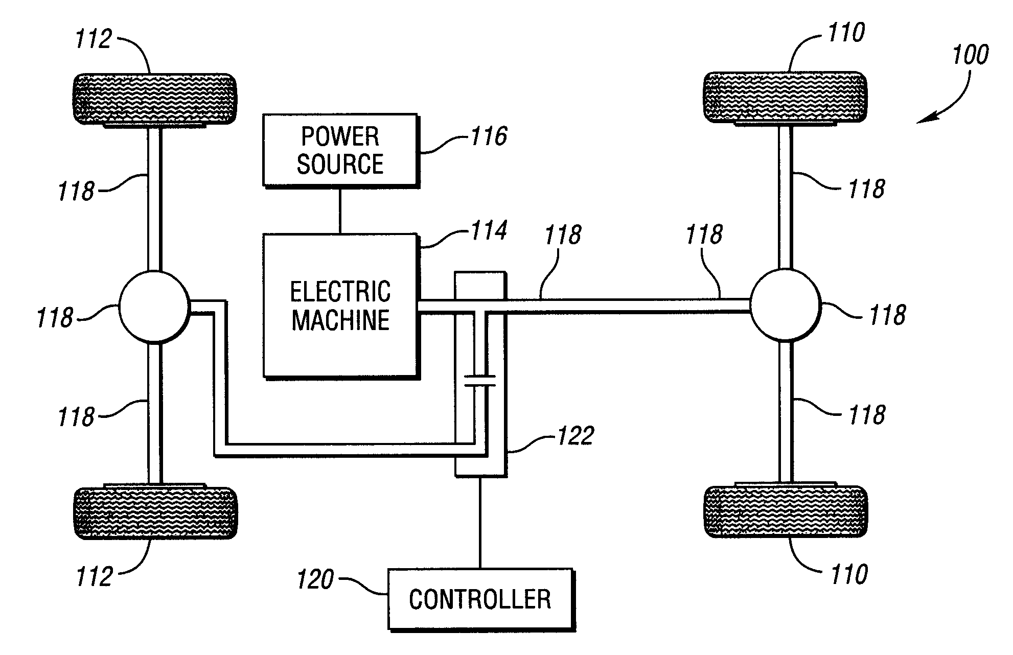
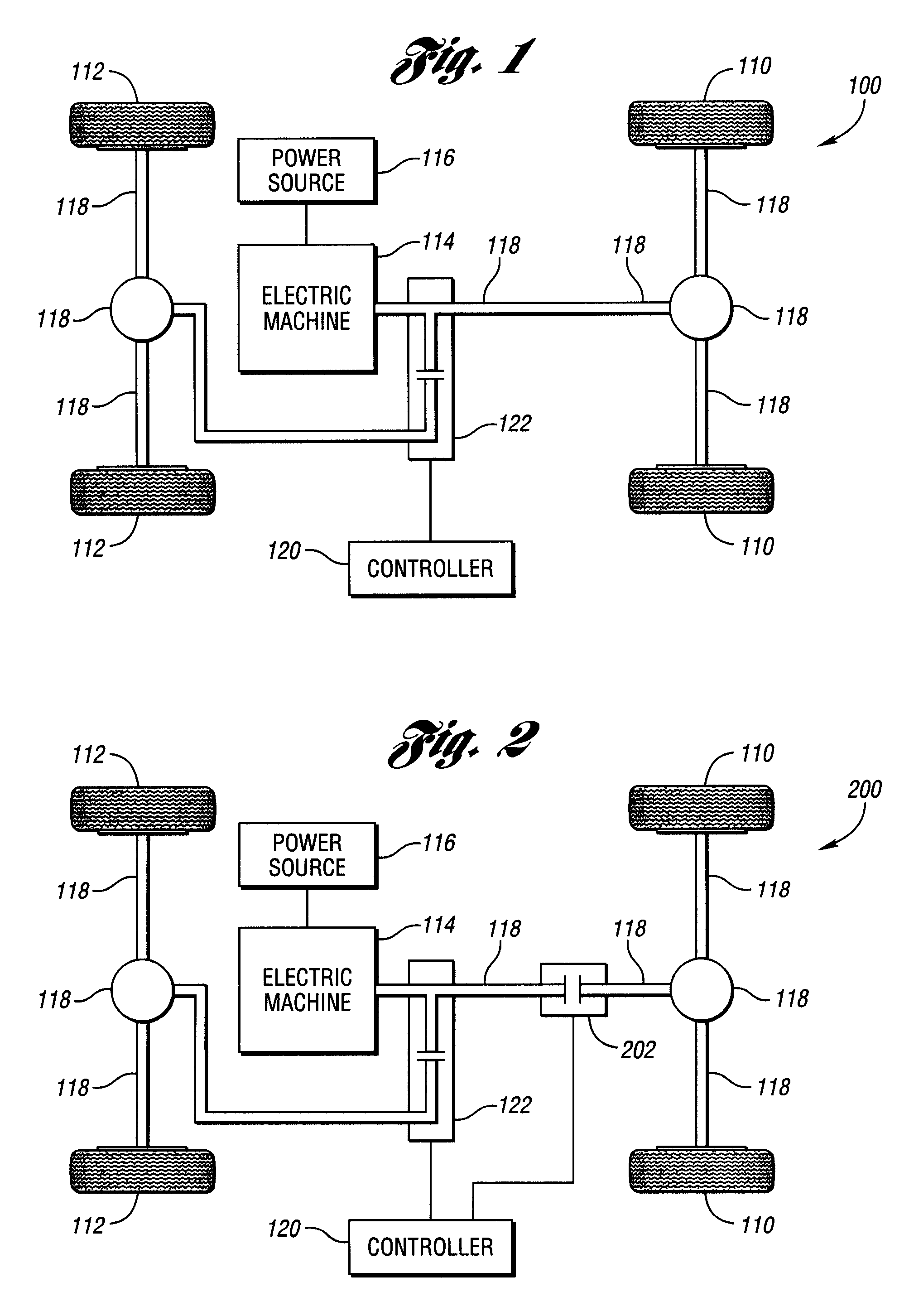
[0019]Referring to FIG. 1, a schematic diagram is provided of a system 100 for recovering regenerative power in an electric (e.g., pure electric, hybrid electric, etc.) vehicle according to an embodiment of the present invention. The system 100 generally comprises a first 110 and second 112 set of vehicle wheels, an electric machine 114, a regenerative power source 116, and a driveline 118. The system 100 may also include a controller 120, such as a Vehicle System Controller (i.e., VSC), for controlling the functionality of one or more components and / or sub-components of the system 100. In general, the controller 120 may be a computer or other logical device which executes programs and / or which performs other logical exercises. It is contemplated that control of the functionality of the one or more components / sub-components of the system 100 may be incorporated into a single controller, such as is shown in FIG. 1. Alternatively, control of the functionality may be distributed among ...


PUM


Abstract

A system, method and vehicle using the same for increasing regenerative power recovered during vehicle deceleration. The system includes first and second sets of vehicle wheels, a controller, an electric machine, a regenerative power source, and a driveline. The electric machine performs as a motor / generator in a first / second mode of operation, respectively. The regenerative power source is electrically coupled to the electric machine and is configured to supply / receive power to / from the electric machine when the electric machine is in the first / second mode of operation, respectively. The driveline is coupled to the electric machine and the first set of vehicle wheels for transferring torque. The driveline includes a controllable coupling apparatus in electronic communication with the controller for selectively coupling, during vehicle deceleration, the electric machine to the second set of vehicle wheels.

Description

BACKGROUND OF THE INVENTION[0001]1. Field of the Invention[0002]The present invention relates generally to a system and method for recovering regenerative power in a vehicle, and more particularly to a system and method for recovering regenerative power in a vehicle having an electric machine.[0003]2. Background Art[0004]Pure electric and hybrid electric vehicles (i.e., electric vehicles) generally include an electric machine for providing, at least in part, tractive force to the vehicle drive wheels. In addition, electric vehicles generally include a power source, such as a battery, an ultra capacitor and / or the like, to supply power to the electric machine.[0005]In general, the energy (e.g., fuel) economy of electric vehicles may be improved by recovering (i.e., capturing) the vehicle's kinetic energy during vehicle deceleration (i.e., brake regeneration). More particularly, during deceleration, braking torque (i.e., negative torque) may be provided to the driven wheels by using t...

Claims


Application Information

Patent Timeline
Patent Type & Authority Patents(United States)
IPC IPC(8): B60K6/00
CPCB60L7/10B60L15/2009Y02T90/16Y02T10/7275B60L2240/423Y02T10/642Y02T10/64Y02T10/7072Y02T10/72
Inventor MASTERSON, BRANDONORTMANN, WALTER
Owner FORD GLOBAL TECH LLC
Why Eureka
Try Eureka