Cement-directing orthopedic implants

a technology of cement-directing orthopedic implants and cement-directing implants, which is applied in the field of orthopedic implants, can solve the problems of minimal total flow resistance or backpressure of the device, and achieve the effects of reducing the amount of cement in the devi

Active Publication Date: 2008-12-16
GLOBUS MEDICAL INC
View PDF128 Cites 184 Cited by
  • Summary
  • Abstract
  • Description
  • Claims
  • Application Information

AI Technical Summary

Benefits of technology

[0017]The primary structure serves to maintain patency of the cavity in which the device is inserted while the bone cement is being injected; it is in that sense that the device is like a stent. (In this regard, a stent or stent-type device may be defined as a structure having sufficient strength in radial compression to maintain the separation of two or more tissue surfaces surrounding a void within a bone defect or fracture, e.g., to maintain manually or otherwise generated separation or distraction of the vertebral endplates during bone cement-based treatment of vertebral fractures.) However, unlike balloons, bags, or other container-type devices that have been used previously to generate and / or maintain separation or distraction, the primary structure of the invention does so without compacting cancellous bone or forming a barrier layer around the cavity. Thus, the cancellous bone at the margins of the bone cavity has relatively normal trabecular architecture, and that fosters beneficial interdigitation of bone cement with the surrounding cancellous bone.
[0018]The flow-directing features of the device, on the other hand, control the direction and rate of bone cement flow when cement is injected into the cavity so as to avoid unwanted cement flow beyond the cortical bone margins or into vascular sinuses or neural structures, all of which can cause clinical complications. Various flow-directing features are contemplated, including (but not limited to) baffles attached to the primary structure, holes or slots selectively formed in the primary structure, and differential porosity of various regions of the primary structure. Possible baffling elements may include co-braided filaments which occupy the spaces of the metal lattice or braid of the primary structure without altering the formability or elasticity of the overall structure, or they may include non-woven secondary films or coatings which adhere to regions of the lattice without altering the formability or elasticity of the structure. Overall, however, the device creates minimal total flow resistance or backpressure and thus directs, rather than contains, cement.

Problems solved by technology

The flow-directing features of the device, on the other hand, control the direction and rate of bone cement flow when cement is injected into the cavity so as to avoid unwanted cement flow beyond the cortical bone margins or into vascular sinuses or neural structures, all of which can cause clinical complications.
Overall, however, the device creates minimal total flow resistance or backpressure and thus directs, rather than contains, cement.

Method used


Image

  • Cement-directing orthopedic implants
  • Cement-directing orthopedic implants
  • Cement-directing orthopedic implants

Examples


Embodiment Construction

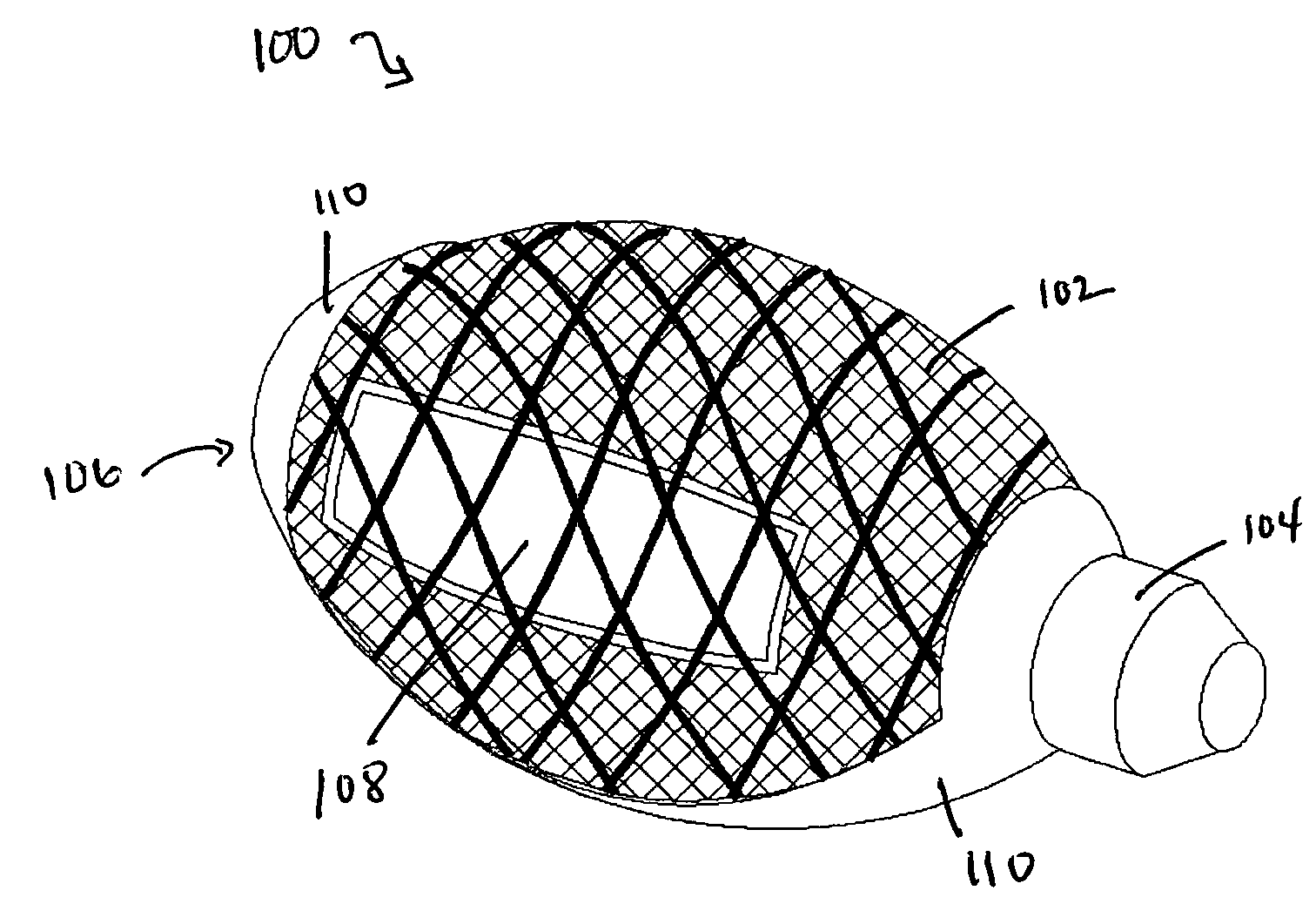
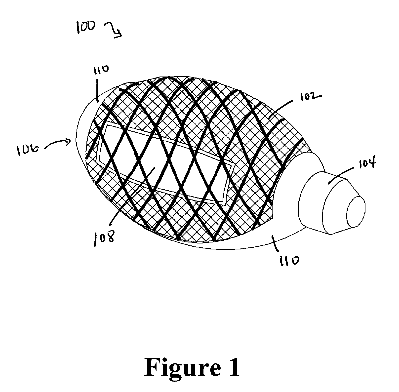
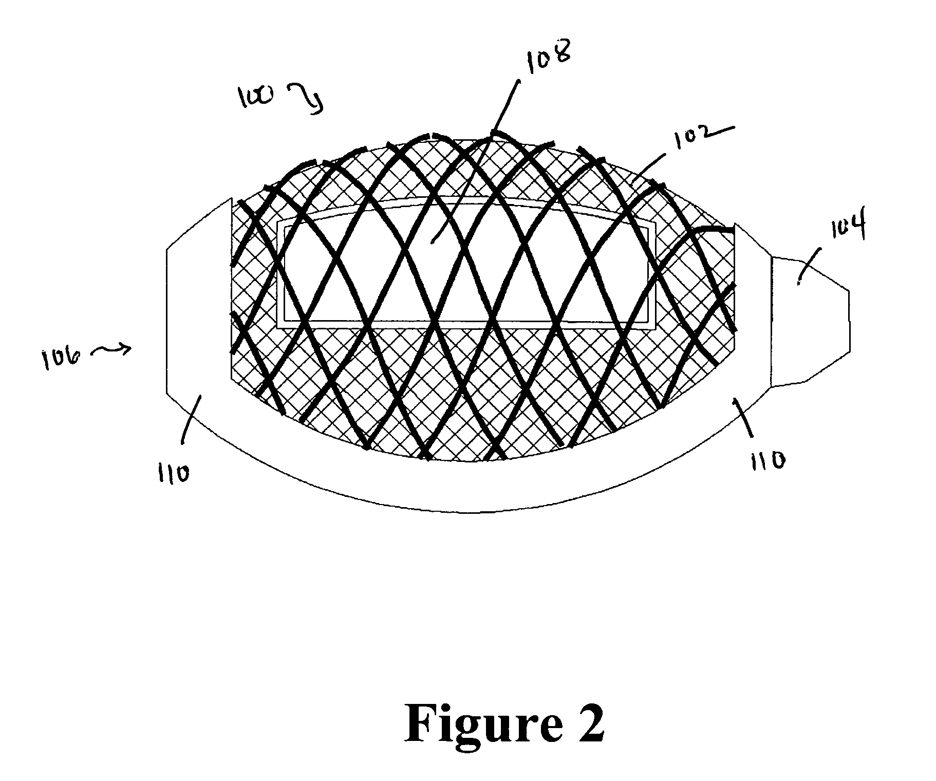
[0030]A first embodiment 100 of a cement-directing structure according to the invention is illustrated in FIGS. 1-11. As illustrated, the hollow structure 100 may be generally ovoid or football-shaped in form (although various other shapes are also contemplated as falling within the scope of the invention, as noted below). In general, the structure 100 features an elastic, self-restoring core member 102 that is crimped, welded, glued, sewn shut, or otherwise closed on one end 104 and open or non-crimped at the opposite end 106; one or more cement flow windows 108 (the illustrated embodiment having a pair of cement flow windows 108); and a flow-retarding baffle member 110. As will be explained in greater detail below, the cement flow windows 108 and the baffle member 110 provide regions of differential cement flow permeability as compared to the surrounding regions of the core member 102, and that differential permeability enables the structure 100 according to the invention to contr...


PUM

PropertyMeasurementUnit
thicknessaaaaaaaaaa
permeabilityaaaaaaaaaa
elasticaaaaaaaaaa

Abstract

A cement-directing structure for use in cement-injection bone therapy includes a collapsible, self-restoring braided structure with regions of differential permeability to the bone cement. The regions of differential permeability may be provided by areas where the braided mesh density is greater or lesser than surrounding areas and / or by means of a baffle. After the structure is placed in a void within a bony structure, cement is injected into the interior of the structure then oozes out in preferred directions according to the locations of the regions of differential permeability.

Description

CROSS-REFERENCE TO RELATED APPLICATIONS[0001]This application is based on and claims priority to provisional U.S. patent application Ser. No. 60 / 562,686 filed Apr. 15, 2004 and provisional U.S. patent application Ser. No. 60 / 604,800 filed Aug. 26, 2004, the contents of both of which are incorporated by reference.FIELD OF THE INVENTION[0002]In general, the invention relates to orthopedic implants. More particularly, the invention relates to devices that are used to facilitate bone cement treatment of vertebral or other bone defects.BACKGROUND OF THE INVENTION[0003]There are many disease states and abnormal conditions that cause defects in the skeleton. For instance, osteoporosis and other metabolic bone conditions weaken the bone structure and predispose the bone to fracture. If not treated, certain fractures and bone defects may progress and lead to the development of severe neurological or other medical complications.[0004]Other examples of bone defects are those resulting from the...

Claims


Application Information

Patent Timeline
Patent Type & Authority Patents(United States)
IPC IPC(8): A61B17/50A61F2/44A61B17/00A61B17/88A61F2/28A61F2/46
CPCA61B17/7098A61F2/441A61B17/00234A61F2/442A61F2/4455A61F2/4601A61F2002/30006A61F2002/30011A61F2002/30583A61F2002/4635A61F2210/0085A61F2250/0015A61F2250/0023
Inventor SENNETT, ANDREW R.GRUBER, WILLIAM HARWICKRICHARD, JOSEPH ERNEST
Owner GLOBUS MEDICAL INC
Why Eureka
Try Eureka