
Laser liner

a laser liner and liner technology, applied in the field of laser liner, can solve the problems of unattractive scrapbook page appearance, untraceable scrapbook pages, and inability to accurately align photos or memories without first sketching, and achieve the effect of convenient and precise positioning

Inactive Publication Date: 2008-12-30
NOTTINGHAM SPIRK DESIGN ASSOCS
View PDF44 Cites 16 Cited by
  • Summary
  • Abstract
  • Description
  • Claims
  • Application Information

AI Technical Summary

Benefits of technology

[0003]The laser liner of the present invention allows for easy and precise positioning of pictures, mementoes, and embellishments in a scrapbook, as well as level journaling and scribing. Thus, the present invention omits the need for written reference lines, which in turn leads to a more attractive scrapbook appearance.

Problems solved by technology

It is known that while scrapbooking, a person typically has trouble easily and accurately aligning photos or mementoes without first sketching in positioning lines.
Sketching in these positioning lines leads to an unattractive appearance of scrapbook pages, as many times the lines cannot be fully erased and remain visible.
Further, sketching in reference lines using a ruler or straight edge with only a visual reference to the edge of scrapbook many times leads to skewed positioning lines, resulting in slanted pictures, keepsakes, and writing.

Method used


Image

  • Laser liner
  • Laser liner
  • Laser liner

Examples


first embodiment

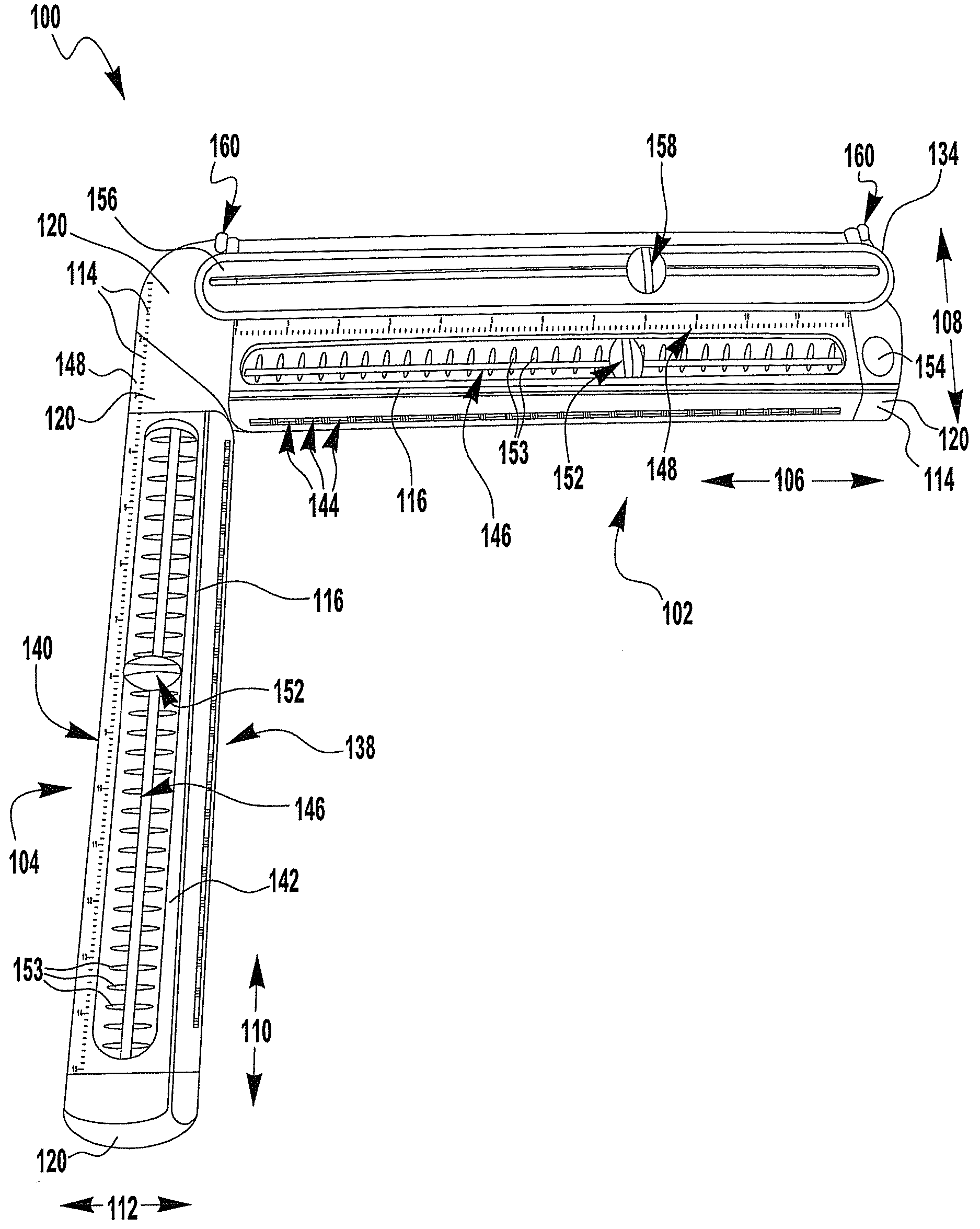
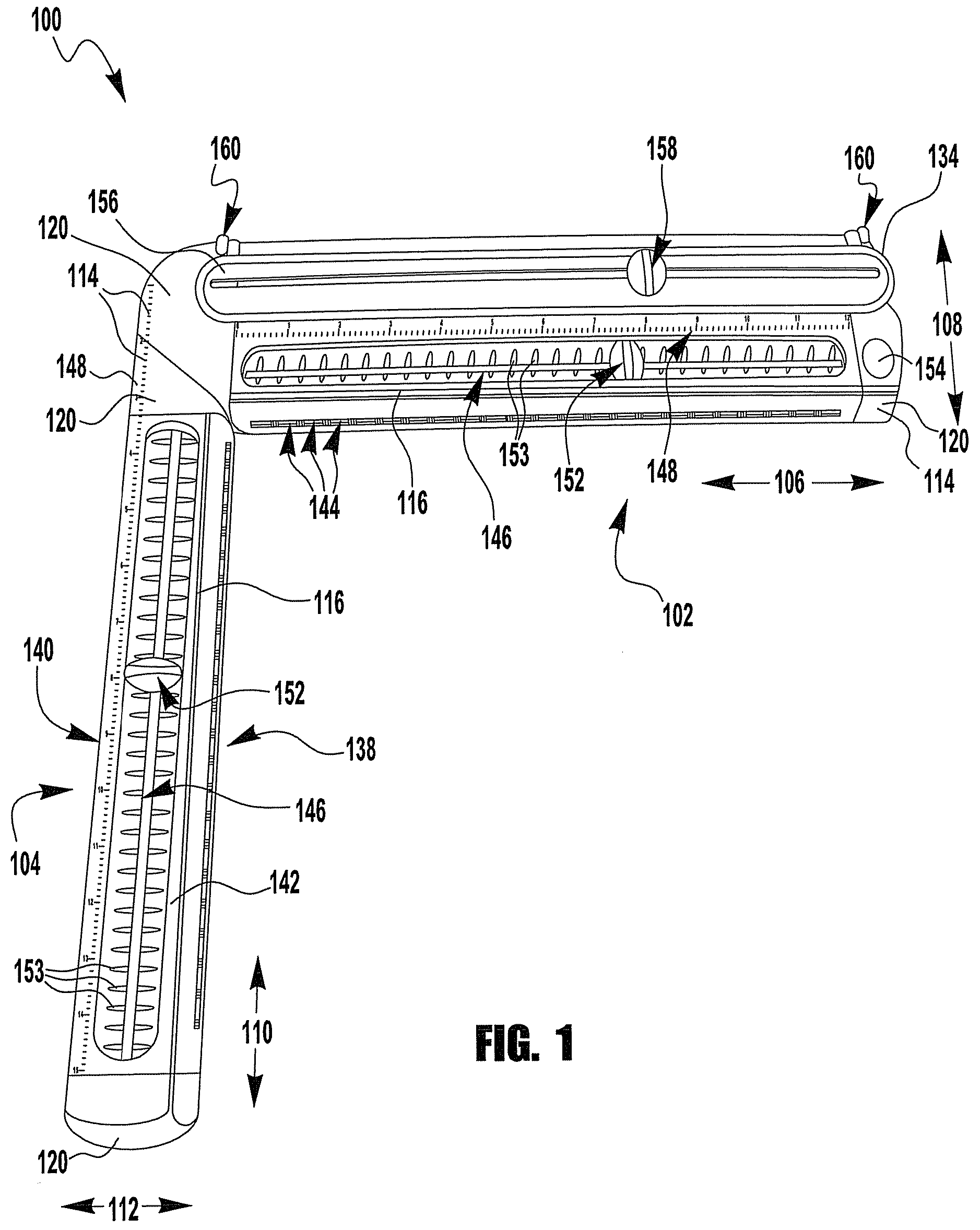
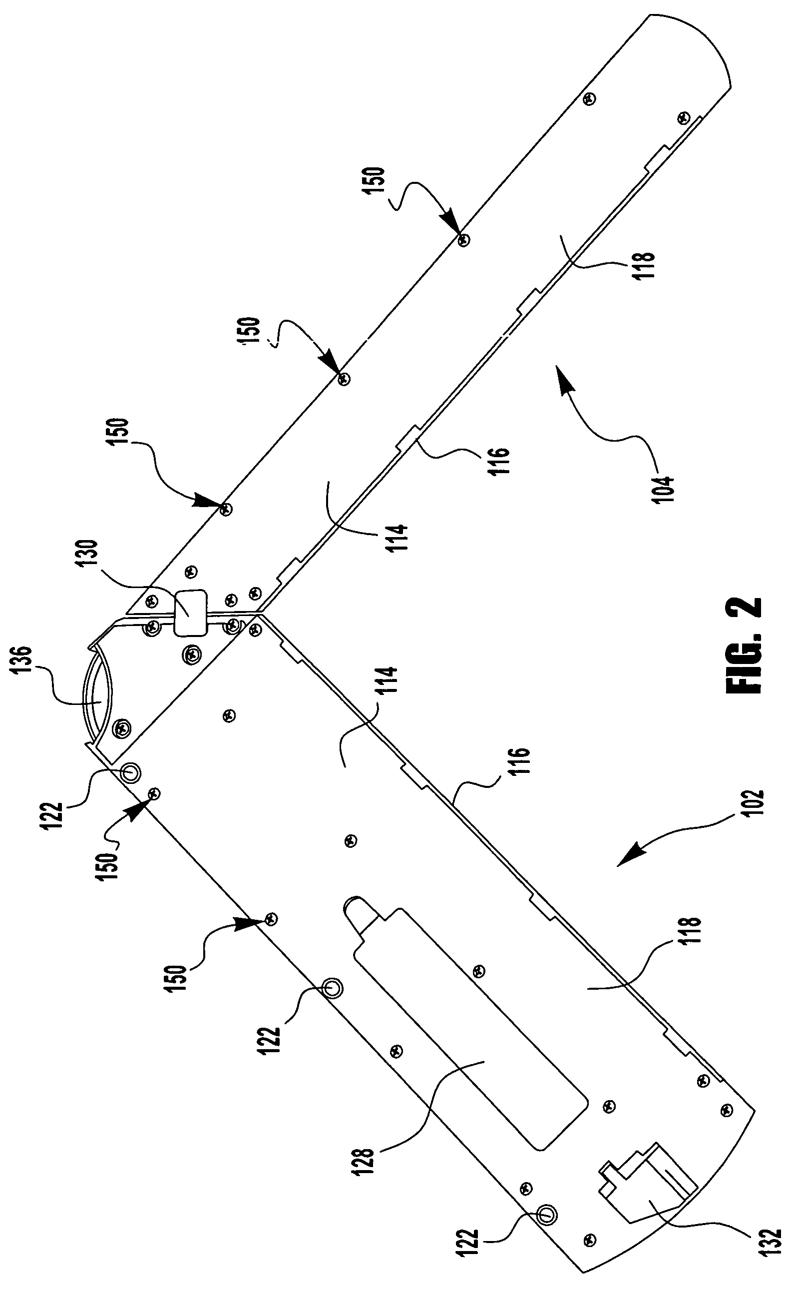
[0018]The laser liner of the present invention generally includes, among other things, at least one elongated arm and a moveably mounted laser. As representative of one embodiment, FIG. 1 illustrates a laser liner 100 in accordance with the invention. As shown in FIG. 1, the laser liner of the illustrated embodiment comprises a major elongated arm 102 and a minor elongated arm 104, each elongated arm having a laser (not shown) moveably mounted within it. Both elongated arms 102,104 have generally elongated rectangular shapes, although one skilled in the art will recognize that other shapes could be used. While the depicted device has two elongated arms, alternate embodiments of the present invention may include only a single arm.

[0019]According to the depicted embodiment, the major elongated arm 102 has a longitudinal dimension 106 and a transverse dimension 108. In some embodiments, the major elongated arm 102 measures about fourteen inches in length along the longitudinal dimensio...

second embodiment

[0050]In accordance with the present invention, the laser liner 100 comprises a single elongated arm and a moveably mounted laser. The laser liner 100 of this embodiment may include some or all of the features of the alternate embodiments mentioned above. This embodiment of the present invention may further include the non-limiting features of a media trimmer, measuring indicia along the longitudinal direction of the elongated arm, multiple moveably mounted lasers, and / or various sources of power.

[0051]In accordance with additional embodiment of the present invention, the laser liner may comprise three or four elongated arms connected together to form a frame, and at least one moveably mounted laser. Referring to FIG. 6, an embodiment of the laser liner 600 comprising a first arms 102, second arm 104, third arm 602 and fourth arm 604 is shown. In certain embodiments, the three or four elongated arms may be permanently locked together with to each other, or other embodiments, may be ...


PUM

PropertyMeasurementUnit
lengthsaaaaaaaaaa
widthsaaaaaaaaaa
widthsaaaaaaaaaa

Abstract

The present invention is directed to a laser liner that may be utilized in the craft of scrapbooking. The laser liner of the present invention may comprise an elongated arm and at least one moveably mounted laser. The elongated arm may have a substantially straight longitudinal edge in which a user may line up a piece of media against it. The moveably mounted laser may be adapted to travel longitudinally along at least a portion of the elongated arm, and when powered, projects a beam upon the media in an orientation perpendicular to the longitudinal edge of the elongated arm.

Description

PRIORITY CLAIM[0001]This application claims priority to U.S. Provisional Patent Application No. 60 / 687,596, entitled “Paper Cutter and Laser Liner,” which was filed Jun. 3, 2005. Application Ser. No. 60 / 687,596 is incorporated herein by reference in its entirety.BACKGROUND OF INVENTION[0002]The present invention is directed to a laser liner. It is known that while scrapbooking, a person typically has trouble easily and accurately aligning photos or mementoes without first sketching in positioning lines. Reference lines are also typically employed when attempting to levelly scribe calligraphy into either a page of a photo album or scrapbook. Sketching in these positioning lines leads to an unattractive appearance of scrapbook pages, as many times the lines cannot be fully erased and remain visible. Further, sketching in reference lines using a ruler or straight edge with only a visual reference to the edge of scrapbook many times leads to skewed positioning lines, resulting in slante...

Claims


Application Information

Patent Timeline
Patent Type & Authority Patents(United States)
IPC IPC(8): B43L7/00B26D7/00F21V33/00
CPCG01C15/002Y10S33/21Y10T83/8822Y10T83/828
Inventor NOTTINGHAM, JOHNSPIRK, JOHNBROWN, PATRICKDORSEY, ROBERTJACKSON, TREVORMCNEELEY, CAROLYN
Owner NOTTINGHAM SPIRK DESIGN ASSOCS
Learn More