Integrated optical focusing/zooming system
a technology of optical focusing and zooming, applied in the field of optics, can solve the problems of reduced transmission efficiency of the system, increased complexity of the structure, and increased complexity of the structure, and achieve the effects of convenient focus and zoom adjustment, simple structure, and high transmission efficiency
- Summary
- Abstract
- Description
- Claims
- Application Information
AI Technical Summary
Benefits of technology
Problems solved by technology
Method used
Image
Examples
first embodiment
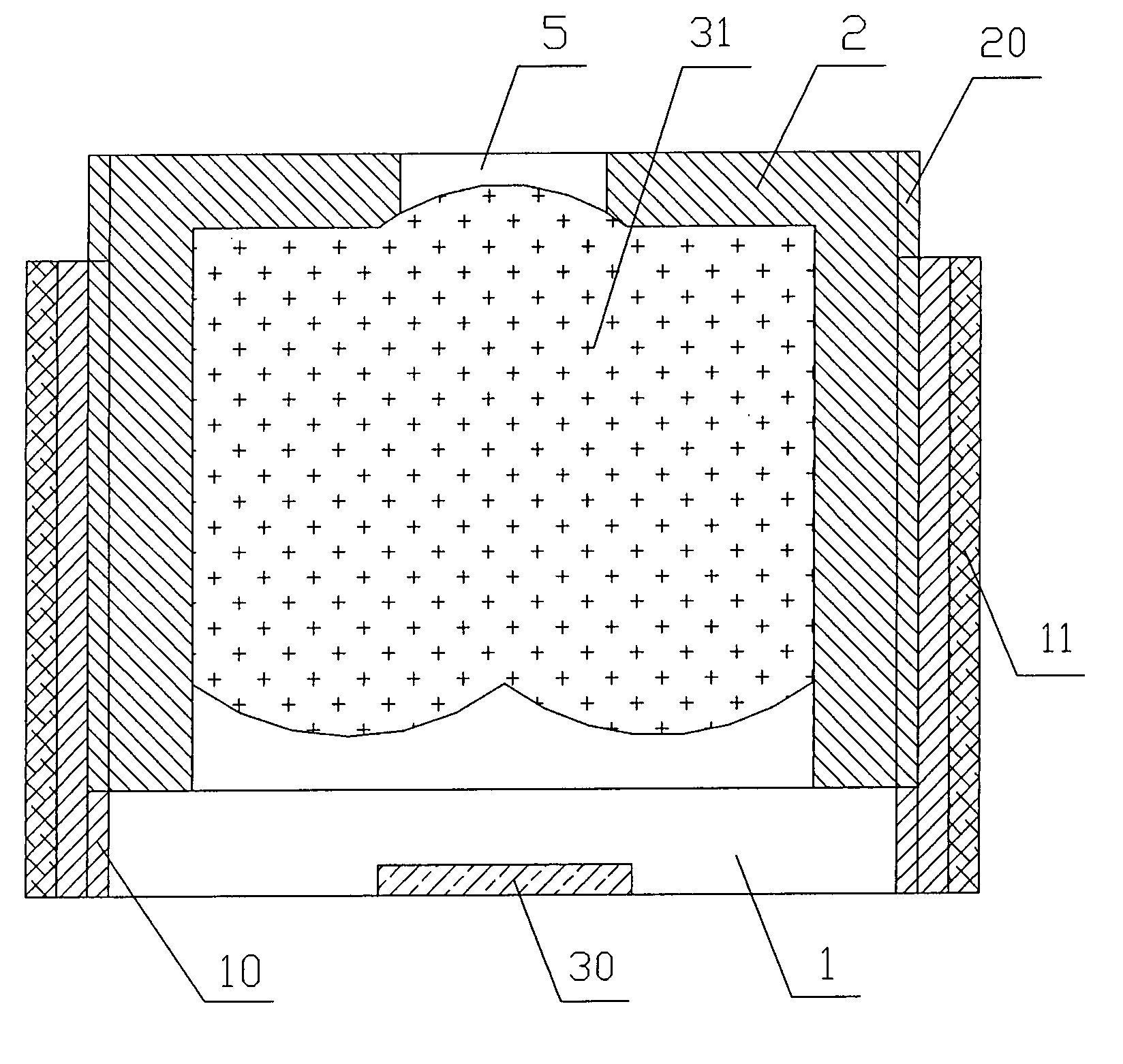
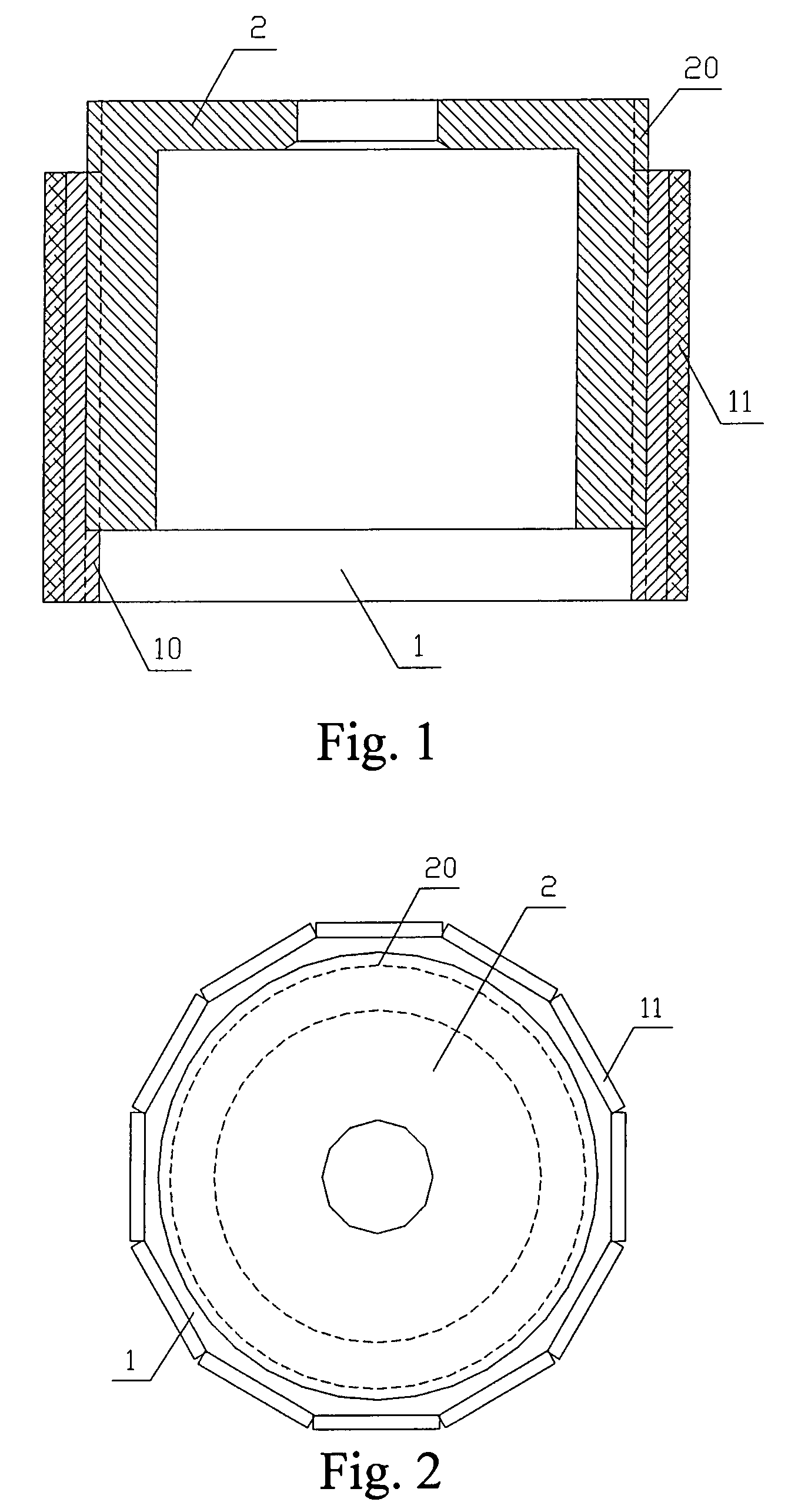
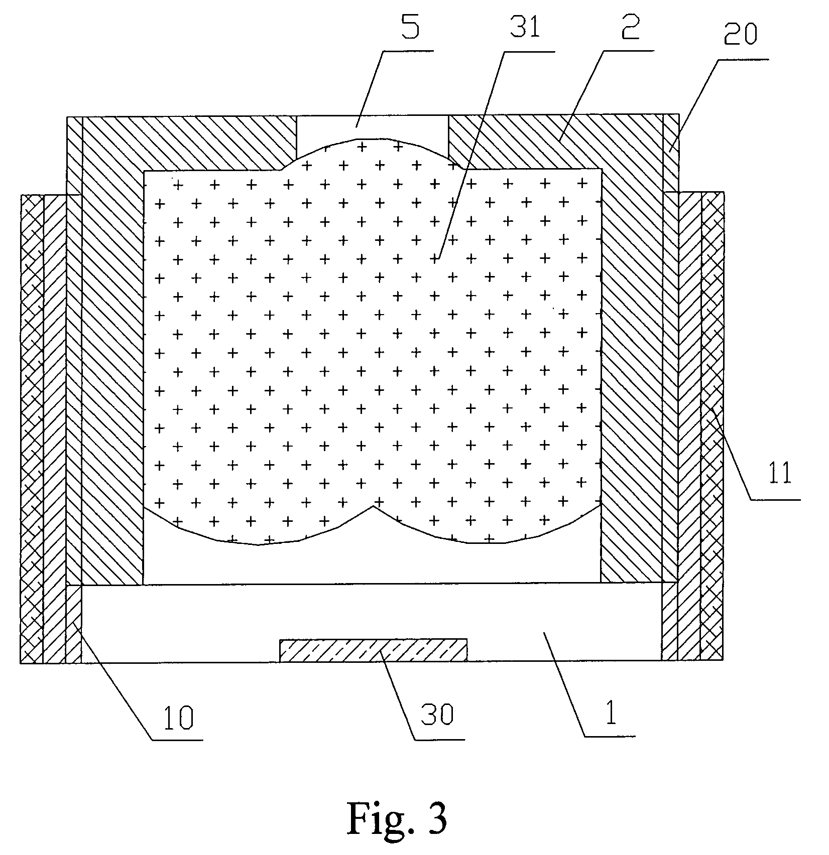
[0038]As shown in FIGS. 1 and 2, an integrated optical auto focus system includes a ring-shaped first casing 2 and a second casing 1 with a cylindrical center hole. The outer surface of the second casing 1 is a regular dodecahedron, twelve piezoelectric elements 11 (the piezoelectric elements 11 may be piezoelectric ceramics, and may be flake-shaped, arc-shaped, column-shaped, or various polyhedron-shaped, overall ring-shaped, cone-shaped, or piecewise circular piezoelectric elements) are respectively adhered on to each of the twelve surface segments of the regular dodecahedron. The second casing 1 is screwed into the first casing 2 through the cylindrical center hole, and the second casing 1 and the first casing 2 are connected through threads at positions where they are in contact. The internal threads 10 are fabricated on the inner wall of the cylindrical center hole of the second casing 1, and the corresponding external threads 20 are fabricated on the outer surface of the first...
second embodiment
[0041]Another integrated optical auto focus and zooming system is shown in FIG. 4. The main difference between FIG. 4 of this embodiment and FIG. 3 of the first embodiment lies in that, in this embodiment of FIG. 4, the second optical lens 32 is placed in the second casing 1, so as to achieve larger focus adjustment range or to reduce the weight of moving parts. As a common practice, an infrared cut glass 50 is placed between the second optical lens 32 and the image sensor 30, so as to prevent infrared light from passing there through. The structures of the other parts in FIG. 4 are the same as or similar to that of FIG. 3 in the first embodiment, which thus will not be described herein.
third embodiment
[0042]As shown in FIG. 5, a third integrated optical auto focus and zooming system includes a ring-shaped first casing 2 and a second casing 1 having a cylindrical center hole. A second optical lens 32 and a third optical lens 33 are placed in the second casing 1. The optical lens 31 is placed in the first casing 2, and the first casing 2 is embedded between the second optical lens 32 and the third optical lens 33 in the second casing 1 and is wrapped by second casing 1 through screw matching. The external threads 20 placed on the cylindrical surface of the first casing 2 are screwed and connected with the internal threads 10 on the inner wall of the second casing 1. The outer side surface of the second casing 1 is a regular dodecahedron, and twelve piezoelectric elements 11 are respectively adhered on to each of the twelve surface segments of the regular dodecahedron. The image sensor 30 is placed at the center position of one end in the second casing 1, an aperture 5 is opened at ...
PUM
 Abstract
Description
Claims
Application Information
 - R&D
- Intellectual Property
- Life Sciences
- Materials
- Tech Scout
- Unparalleled Data Quality
- Higher Quality Content
- 60% Fewer Hallucinations
Browse by: Latest US Patents, China's latest patents, Technical Efficacy Thesaurus, Application Domain, Technology Topic, Popular Technical Reports.
© 2025 PatSnap. All rights reserved.Legal|Privacy policy|Modern Slavery Act Transparency Statement|Sitemap|About US| Contact US: help@patsnap.com


