Combined impeller

A combined, impeller technology, used in non-variable volume pumps, components of pumping devices for elastic fluids, machines/engines, etc., can solve problems such as difficult positioning, insufficient strength, and easy deformation.

Inactive Publication Date: 2010-03-10
杨圣安
View PDF1 Cites 6 Cited by
  • Summary
  • Abstract
  • Description
  • Claims
  • Application Information

AI Technical Summary

Problems solved by technology

[0005] However, although the design of this cooling fan has a centrifugal effect to increase the wind pressure, the inner edge of the upper blade 622 is designed to correspond to the guide surface, so that the inner edge structure of the upper blade 622 is gradually lower from the middle to the outer periphery. ,

Method used


Image

  • Combined impeller
  • Combined impeller
  • Combined impeller

Examples


Embodiment Construction

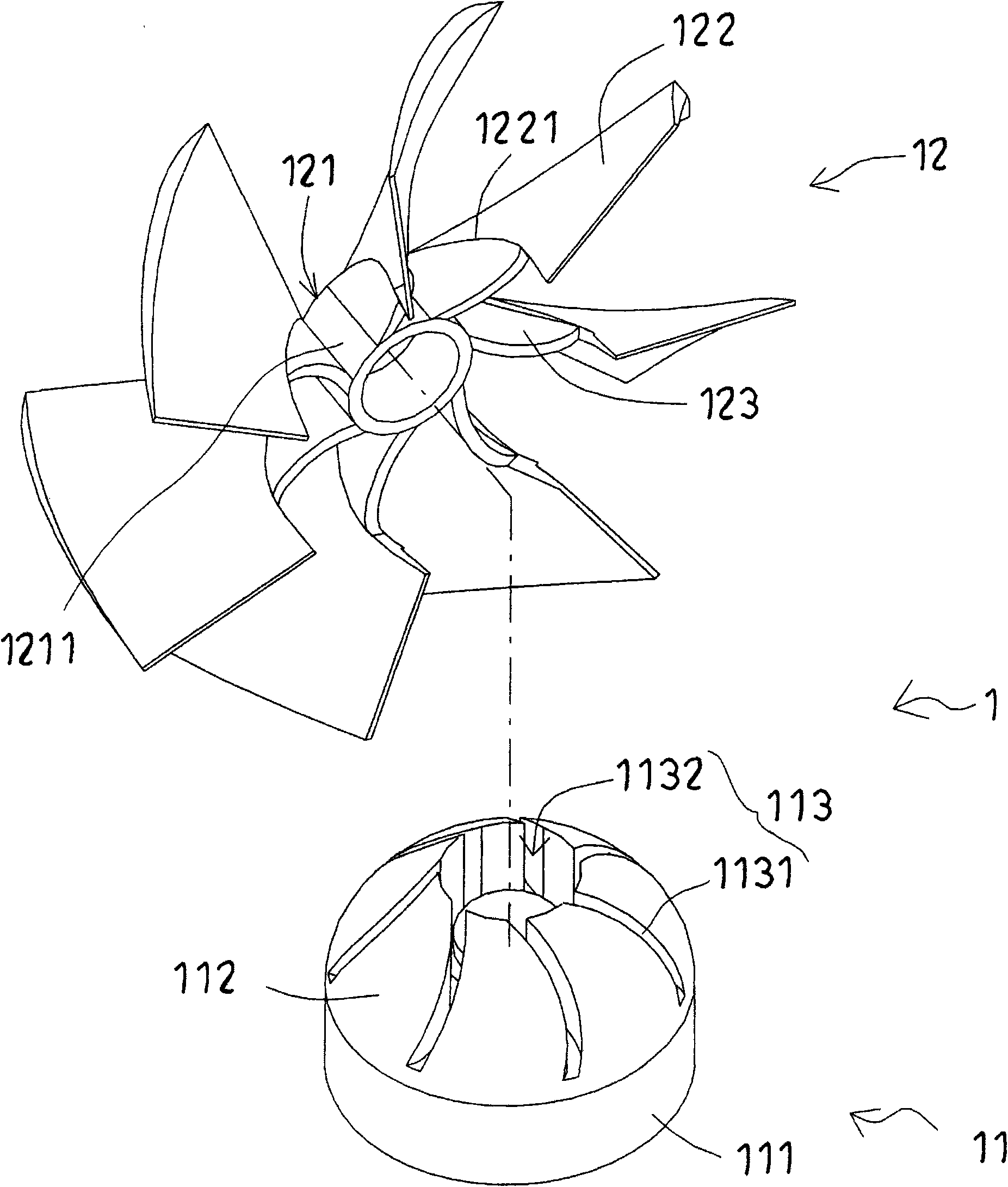
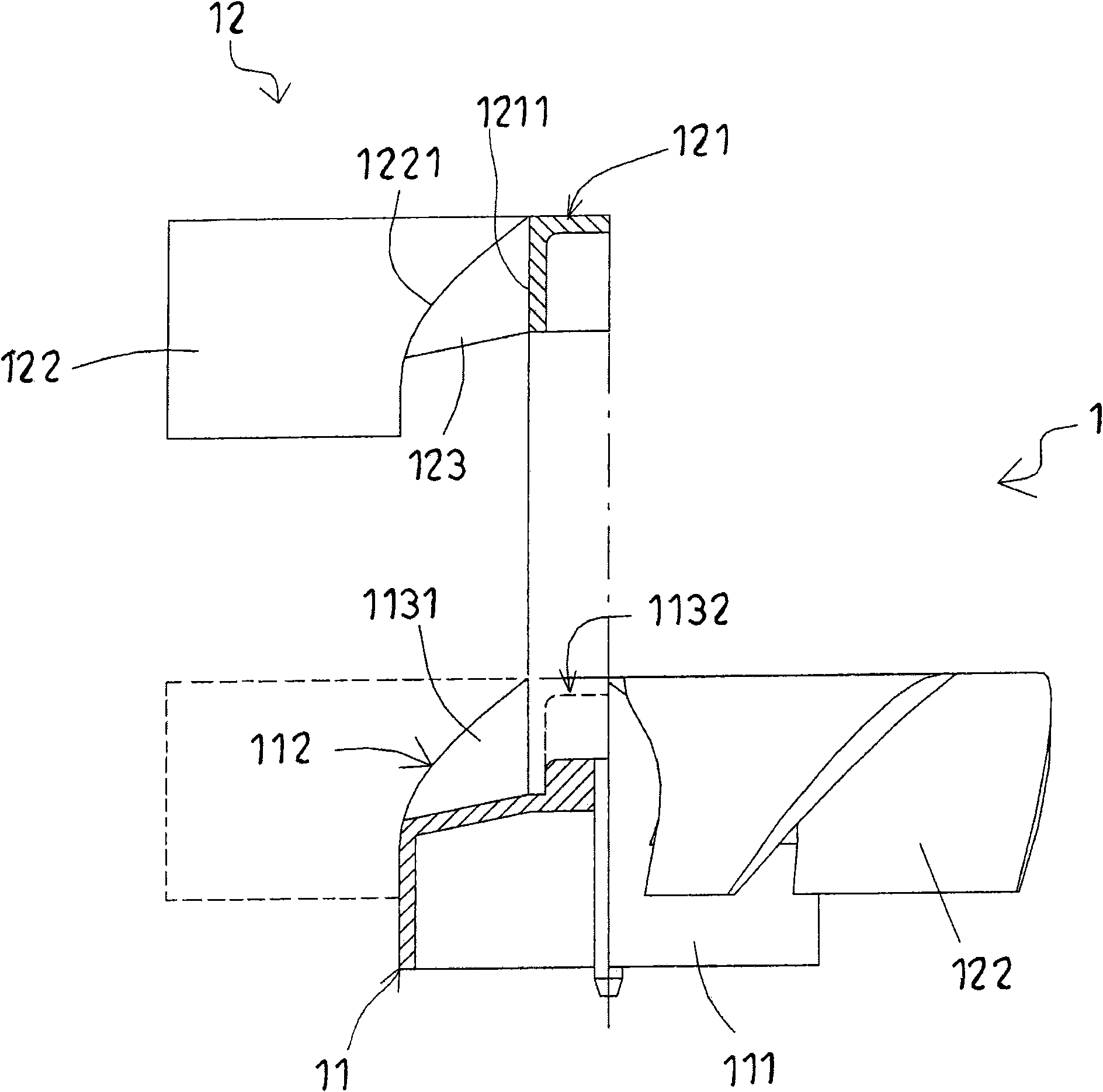
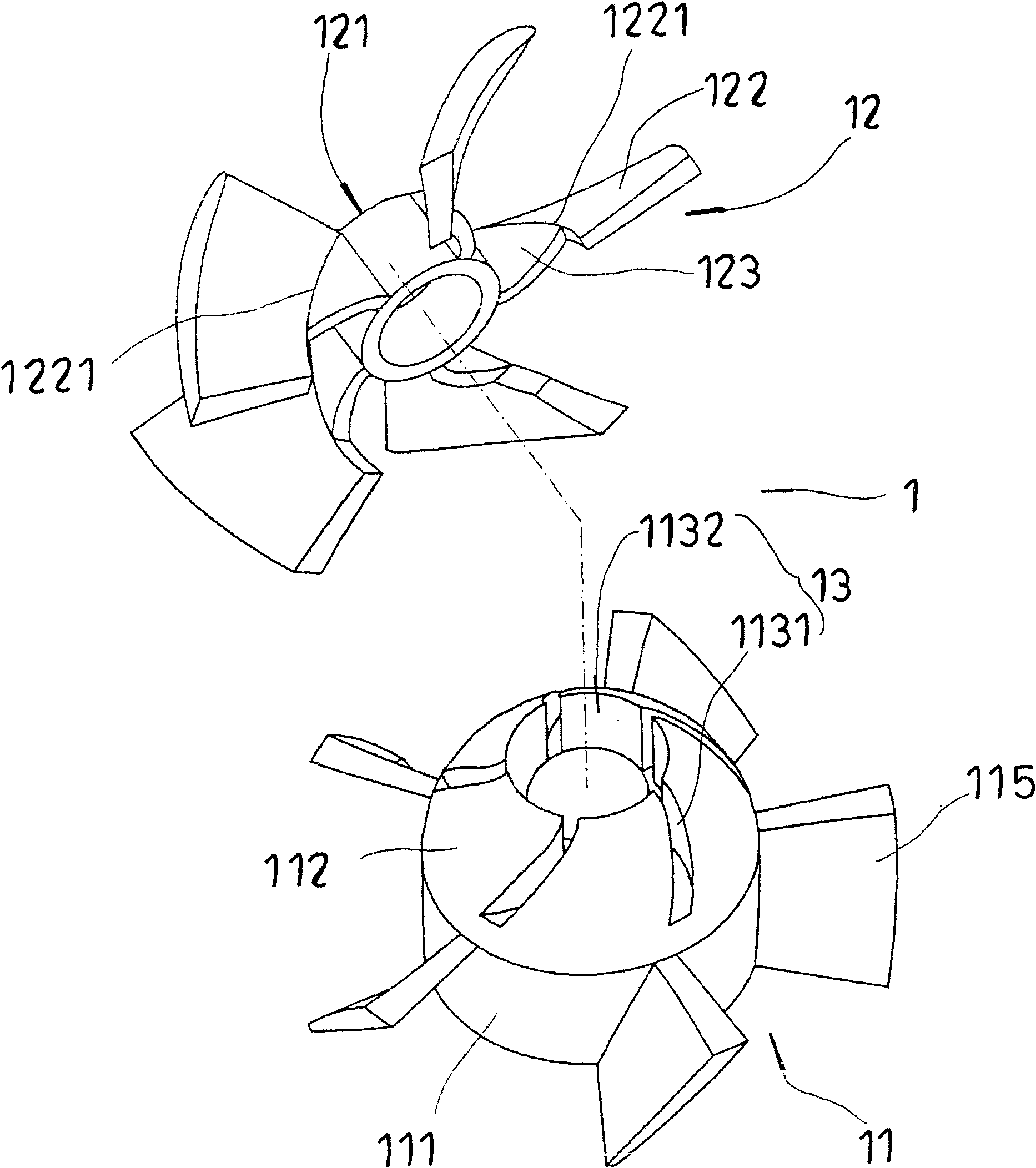
[0068] Please cooperate with reference figure 1 , figure 2 As shown, it is the first preferred embodiment of the combined impeller of the present invention; the combined impeller 1 includes: an annular seat 11 and an impeller 12; wherein:

[0069] The annular seat body 11 has a hub 111, the hub 111 is provided with an arc-shaped diversion surface 112, and a ring body hole group 113 is arranged on the annular seat body 11, and the ring body hole group 113 includes a plurality of concave holes. The card groove 1131 and a recessed ring body hole 1132, and each card groove 1131 communicates with the ring body hole 1132 and the flow guide surface 112; in addition, the annular seat 11 can further be provided with several booster blades at the periphery 114 (please refer to Figure 6 ), each supercharging vane 114 is located in the trailing edge of the air passage between two adjacent vanes 122 of the impeller 12;

[0070] There is a ring body 121 embedded in the ring body hole ...


PUM


Abstract

The invention discloses a combined impeller. At least one impeller is arranged in an annular seat body, wherein the annular seat body is provided with a guide surface and is also provided with at least one annular body hole group, the annular body hole group comprises a plurality of concave clamping grooves and a concave annular body hole, and each clamping groove is communicated with the annularbody hole and the guide surface; and the impeller is provided with an annular body which is embedded into the annular body hole of the annular seat body, a plurality of blades encircle the periphery of the annular body, reinforcing sheets for connecting the annular body and the blades are arranged between the inner edges of the blades and the periphery of the annular body, the reinforcing sheets are correspondingly embedded into the clamping grooves, the inner edges of the blades and the guide surface have the same shape and are matched, and air passages are formed between the two adjacent blades and in a section formed by the annular seat body. Through the design, the weak sections formed between the annular body and the blades can be eliminated, so the impeller is not easy to deform, andaccurate positioning and combination between the impeller and the annular seat body are favorable.

Description

technical field [0001] The invention relates to a combined impeller, in particular to a combined impeller which overcomes the interference of mold release by using a combined method, increases the strength of the impeller component, prevents deformation, and precisely positions to improve product quality. Background technique [0002] Please refer to Chinese Patent No. ZL01268180.6 "Combined Cooling Fan" for existing cooling fans (please refer to Figure 11 ), the combined cooling fan 4 includes a lower fan body 41 and an upper fan body 42, the lower fan body 41 has a body 411 whose top surface protrudes into a cone shape, and a sleeve shaft 412 protrudes from the center of the top surface of the body 411, A plurality of lower blades 413 protrude from the outer periphery of the main body 411, and the top surface of the main body 411 extends outward from the periphery of the sleeve shaft 412 to have a number of locking grooves 414 corresponding to the lower blades 413. The out...

Claims


Application Information

Patent Timeline
IPC IPC(8): F04D29/26F04D29/34
Inventor 杨圣安
Owner 杨圣安
Why Eureka
Try Eureka