Drive shaft for use in portable working machine

Inactive Publication Date: 2006-02-14
HONDA MOTOR CO LTD
View PDF12 Cites 7 Cited by
  • Summary
  • Abstract
  • Description
  • Claims
  • Application Information

AI Technical Summary

Benefits of technology

[0021]In the inventive method, the resin bushes can be successively integrally molded on the drive shaft. Thus by the simple method, the resin bushes can be easily integrally formed on the outer peripheral surface of the drive shaft to be inserted through the pipe-shaped operating pole.
[0022]Further, the integral molding of the bushes on the drive shaft allows precise agreement of the axis center of the resin bushes with the axis center of the drive shaft. In addition, the resin bushes can be easily and precisely positioned in the longitudinal direction of the drive shaft.
[0023]Further, according to the method of this in

Problems solved by technology

Further, the peripheral grooves can store the lubricant such as grease and oil, increasing lubricity

Method used


Image

  • Drive shaft for use in portable working machine
  • Drive shaft for use in portable working machine
  • Drive shaft for use in portable working machine

Examples


Embodiment Construction

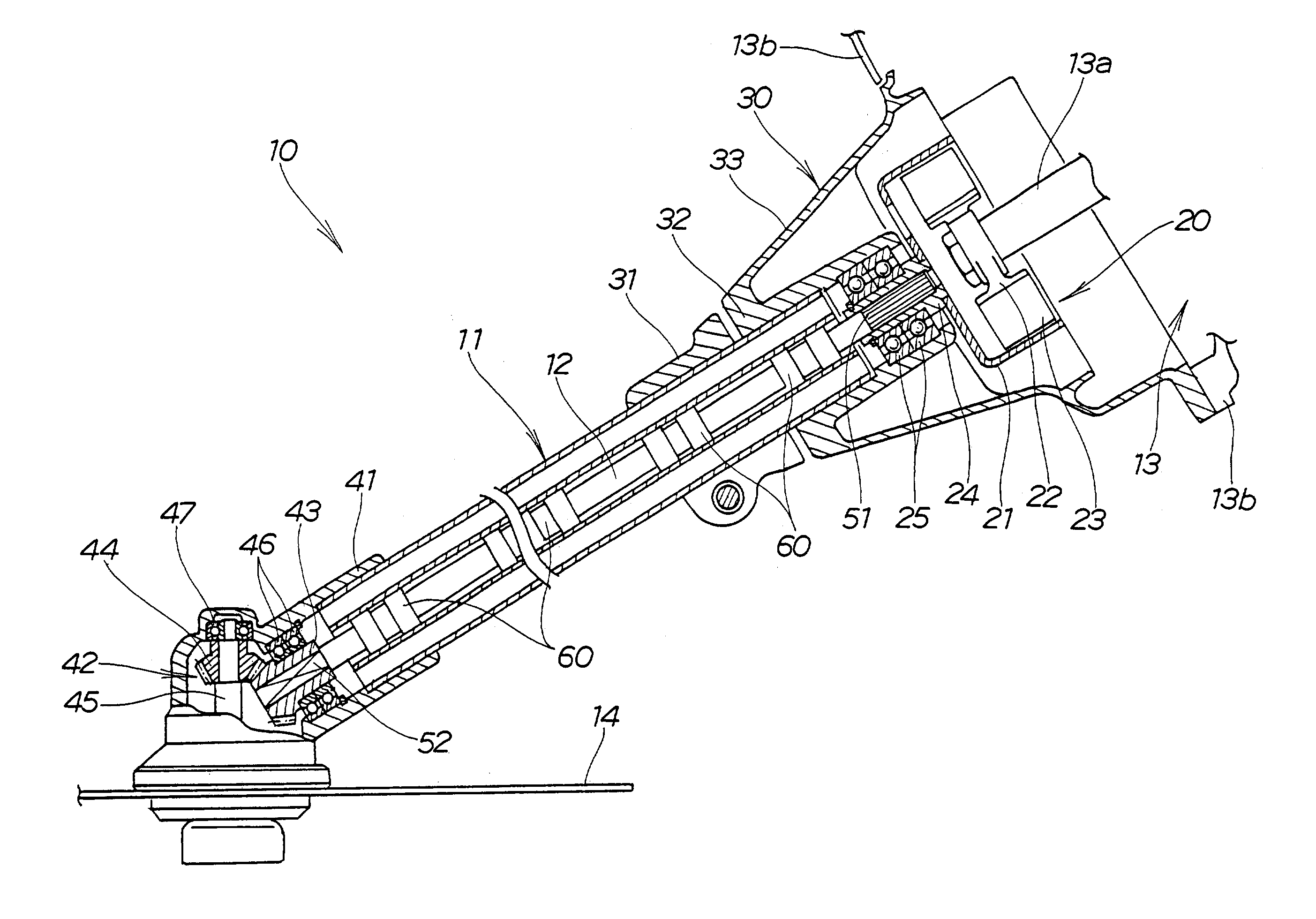
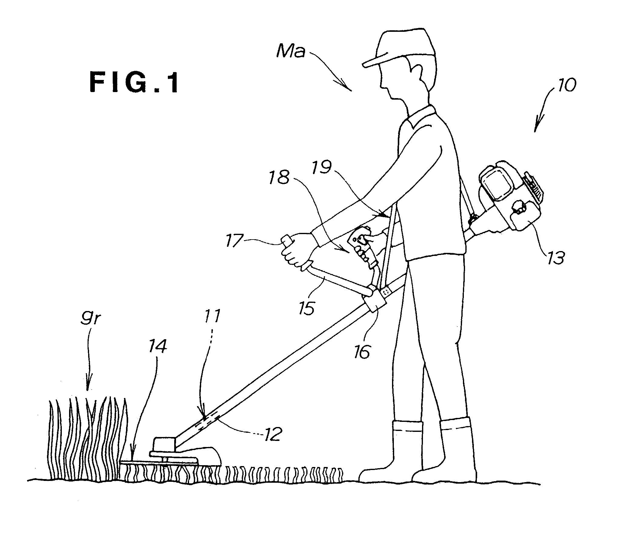
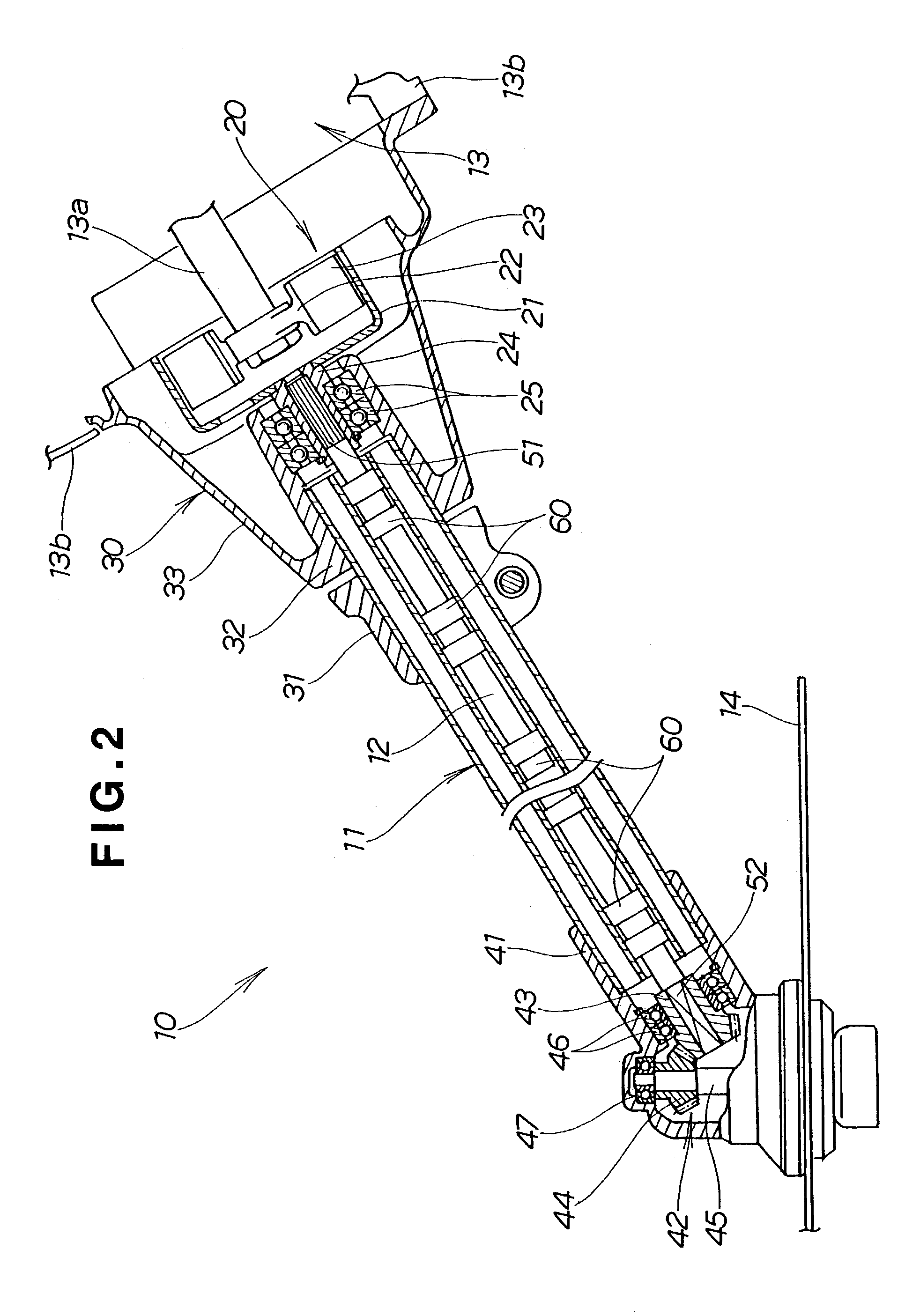
[0037]Initial reference is made to FIG. 1 showing a grass cutter 10 as an example of a portable working machine. The grass cutter 10 includes a tubular member or pipe-shaped operating pole 11, a motor 13 provided at one end of the operating pole 11, a drive shaft 12 inserted into the operating pole 11 and driven by the driving of the motor 13, and a work implement such as a cutting blade 14 provided at the other end of the operating pole 11 and rotated by the rotation of the drive shaft 12. The grass cutter 10 has a handle holder 16 for fixing a handle 15 at a longitudinally midway point of the operating pole 11, forming a crisscross in a plan view. The motor 13 is an engine or an electric motor. The cutting blade 14 is a working portion.

[0038]The bar-shaped handle 15 has a substantially U shape in a front view and is made from a pipe material or a bar member, extending left and right with a central part mounted on the operating pole 11, and having a left grip 17 and a right grip 18...


PUM


Abstract

A drive shaft extends into a tubular member for use in a portable working machine. The drive shaft is mounted relative to the tubular member so as to undergo rotation relative to the tubular member. The drive shaft has a longitudinal axis and resin bushes integrally mounted on the drive shaft for rotation therewith at positions along the longitudinal axis corresponding to vibration nodes of the drive shaft. Each of the resin bushes has an outer peripheral surface disposed in slidable contact with an inner peripheral surface of the tubular member.

Description

FIELD OF THE INVENTION[0001]1. Background of the Invention[0002]The present invention relates to an improvement in drive shafts for use in portable working machines such as grass cutters, and a method for forming bushes on the drive shafts.[0003]2. Background Information[0004]In some conventional work machines, drive shafts are inserted into tubular operating poles and rotated by motors provided at one ends of the operating poles to rotate working portions provided at the other ends of the operating poles. These conventional working machines include grass cutters, for example.[0005]In the conventional grass cutters, the motors are driven to rotate the drive shafts, rotating cutting blades provided at the other ends of the operating poles. Operators hang the grass cutters on them with belts and hold bar-shaped handles provided at midway points of the operating poles to move the operating poles back and forth and left and right, thereby cutting grass with the cutting blades.[0006]In r...

Claims


Application Information

Patent Timeline
IPC IPC(8): F16C3/035A01D34/68A01D34/90F16C3/02
CPCA01D34/905F16C3/02Y10T464/50F16C2310/00F16F15/08F16F15/10A01D34/76
Inventor SASAKI, HIDESHIWARASHINA, MAKOTOUCHITANI, HIROAKI
Owner HONDA MOTOR CO LTD
Why Eureka
Try Eureka