Micromachine structure

a micro-mechanical and structure technology, applied in the field of micro-mechanical structure, can solve the problems of increasing the cost, affecting the quality of micro-mirrors, so as to reduce the weight light-weighted, and highly rigid. the effect of the movable section

Inactive Publication Date: 2009-11-12
PANASONIC CORP
View PDF4 Cites 5 Cited by
  • Summary
  • Abstract
  • Description
  • Claims
  • Application Information

AI Technical Summary

Benefits of technology

[0038]In accordance with a micro-mechanical structure of the present invention, two plate portions are coupled via a “link portion” which is preferably implemented as a vertical rib, so that a light-weighted and highly rigid movable section is obtained. In a preferable embodiment, the movable section is formed of a thin metal film, a part of which functions as a mirror. In such a case, even if the thin metal film is made thin in order to reduce the weight of the movable section, the movable section maintains a good planarity, so that a micromirror device capable of being rapidly driven can be realized at a low cost.
[0039]Moreover, a micro-mechanical structure according to the present invention can suitably be produced by using an MEMS process which is CMOS-interchangeable, and therefore can be easily integrally formed on a wafer having CMOS circuitry.

Problems solved by technology

Firstly, in a micromirror array in which a multitude of mirrors are independently driven, the actuators and mirror portions need to be formed integrally with the driving circuit. In order to achieve such integration, it would be efficient to not only form CMOS circuitry on one semiconductor wafer but also to sequentially form actuator portions, mirror portions, and the like, whereby cost can be reduced.
However, since the mirrors are formed from a thin metal film, the mirrors are likely to be warped due to a stress gradient along the thickness direction that occurs during the film formation step.
If the mirrors are warped, it becomes impossible to control the wave aberration of reflected light by using the micromirror array.
This results in complicated processes, e.g., performing separate film formations and using an oxide film as an etch stop, which increases the cost.
If the yoke were to be concurrently formed, with the same thickness as that of the twist hinge, the yoke would be deformed due to electrostatic attraction and the mirrors would not be accurately driven.
However, a multitude of dents would occur on the mirror surface corresponding to the mirror supporting posts, which would increase the influences of scattering and diffraction of reflected light and therefore not be preferable.

Method used


Image

  • Micromachine structure
  • Micromachine structure
  • Micromachine structure

Examples


embodiment 1

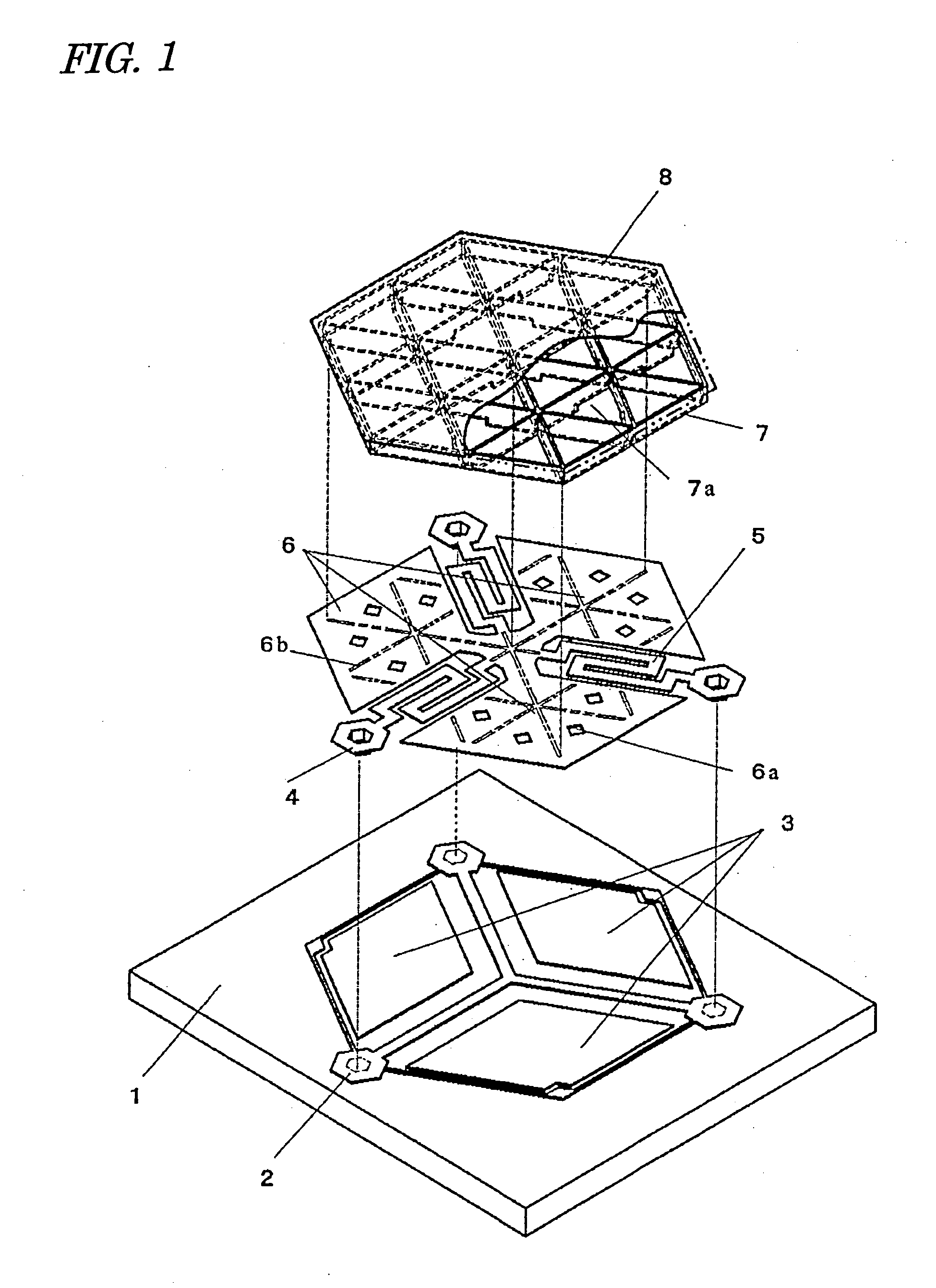
[0092]First, with reference to FIG. 1, a first embodiment of a micro-mechanical structure according to the present invention will be described. FIG. 1 is an exploded perspective view showing a micro-mechanical structure according to the present embodiment, where a mirror is partly cut away so as to show an underlying rib structure.

[0093]A base 1 according to the present embodiment includes a silicon substrate on which CMOS circuitry is formed and a planarized insulating layer with which an upper face of the silicon substrate is coated.

[0094]On the insulating layer of the base 1, a ground electrode 2 and three stationary electrodes 3 are provided. The ground electrode 2 and the stationary electrodes 3 are formed of an electrically conductive material which is capable of being deposited at a temperature of 450° C. or less. Such an electrically conductive material may be an aluminum (Al) alloy or polysilicon germanium (Poly-SiGe), for example. The ground electrode 2 and the stationary ...

embodiment 2

[0127]In Embodiment 1, the three elastic supporting members 5 and the movable electrode 6 are present on the same plane, and are formed of the same electrically conductive material. The planar layout of the elastic supporting members and the movable electrode is not limited to that shown in Embodiment 1.

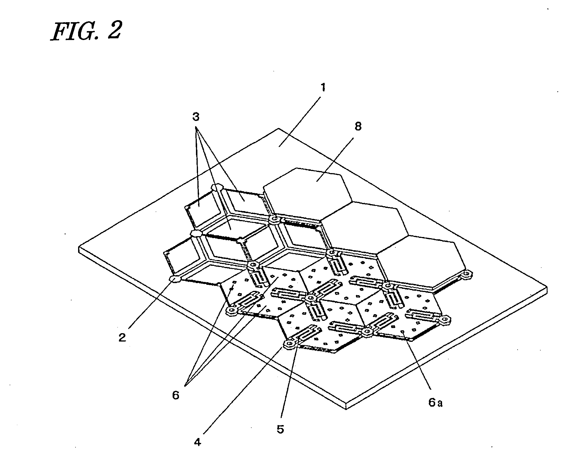
[0128]FIG. 6 shows a planar layout of another exemplary construction of the elastic supporting members 5 and the movable electrode 6. In the present embodiment, along the outer periphery of a hexagonal movable electrode 26, elastic supporting members 25 extend from three support posts 24, so as to link to a movable electrode 26. Below the movable electrode 26, three stationary electrodes 23 shown by broken lines are disposed.

[0129]In the present embodiment, too, the elastic supporting members 25 and the movable electrode 26 are suitably formed by patterning the same metal film. Other than the elastic supporting members 25 and the movable electrode 26, the construction is similar to t...

embodiment 3

[0130]The shape of the movable electrode does not need to be hexagonal. FIG. 7 shows a square movable electrode 36. In the present embodiment, along the outer periphery of a movable electrode 36 having a square shape, elastic supporting members 35 extend from four support posts 34, so as to link to the movable electrode 36. Below the movable electrode 36, four stationary electrodes 33 shown by broken lines are disposed.

[0131]The number of stationary electrodes within each unit cell is not limited to 3 or 4, but may be 2, or 5 or more. However, in order to realize displacement along three axes, it is preferable to assign three or more stationary electrodes to one movable electrode.

[0132]As is illustrated in Embodiments 1 to 3 above, the movable electrode and the mirror are coupled via vertical ribs (link portions), whereby the movable section can have both a light weight and a high rigidity. Moreover, there is provided an increased design freedom for the elastic supporting members in...


PUM

PropertyMeasurementUnit
areaaaaaaaaaaa
areaaaaaaaaaaa
thicknessaaaaaaaaaa

Abstract

A micro-mechanical structure according to the present invention includes: a base 1; an elastic supporting member 5 having elasticity, the elastic supporting member 5 being formed on the base 1; and a movable section supported by the elastic supporting member 5 so as to be capable of making a relative move with respect to the base 1. This movable section includes a movable electrode 6 opposing the base 1 via a first gap, and a mirror 8 being affixed to the movable electrode 6 via a vertical rib 7.

Description

TECHNICAL FIELD[0001]The present invention relates to a micro-mechanical structure, and various devices having the micro-mechanical structure.BACKGROUND ART[0002]Various micromirror devices have been devised as micro-mechanical structures to which micromachining technology is applied, and their applications to optical scanning apparatuses such as laser printers, scanners, and displays, and optical switching devices to / from which input / output of optical fibers is switched are under study.[0003]Patent Document 1 discloses a reflection-type optical modulation device having an array of micromirrors. This device has been developed as an image displaying device of a video projector, and is known as a DMD (Digital Micromirror Device). Micromirrors of the DMD are formed on CMOS circuitry.[0004]The DMD which is disclosed in Patent Document 1 includes: a bias bus and a pair (left-right) of address electrodes as metal members in a first layer (lowermost layer) upon an oxide film; a twist hinge...

Claims


Application Information

Patent Timeline
Patent Type & Authority Applications(United States)
IPC IPC(8): G02B26/08G11B7/135
CPCG02B26/0841G11B7/13925G11B7/1362
Inventor KUROZUKA, AKIRATOMITA, HIRONORIMUSHIKA, YOSHIHIRO
Owner PANASONIC CORP
Why Eureka
Try Eureka