Connection device

a technology of connecting device and flange, which is applied in the direction of hose connection, flanged joint, borehole/well accessories, etc., can solve the problems of inability to finely set or remove the deflecting bushing, and the adjustment of the hydraulic driving means and thus the deflecting bushing cannot be controlled under great efforts, so as to achieve simple constructive measures, control the effect of fine setting and low cos

Inactive Publication Date: 2008-12-30
ONESUBSEA IP UK LTD
View PDF10 Cites 12 Cited by
  • Summary
  • Abstract
  • Description
  • Claims
  • Application Information

AI Technical Summary

Benefits of technology

[0008]Improving a connection device in such a way that an exactly reproducible displacement of the deflecting bushing is possible by simple constructive measures and without high costs, which also permits a controlled fine setting, is achieved according to a connection device for connecting a tubular member to another member that comprises a clamp ring arranged in an inner bore of an outer housing, where the clamp ring comprises a plurality of clamping fingers which are deflectable essentially in a radial direction relative to the outer housing inner bore. The connection device also includes a deflecting bushing which is displaceable by at least one driving means in an axial direction of the inner bore between a stand-by position and a deflecting position, the clamping fingers being radially inwardly deflected when the deflecting busing is in the deflecting position. The driving means comprises a rotatable, axially not displaceable spindle along which said deflecting bushing is movable.
[0009]Since the deflecting bushing is movable along a rotatable spindle, the displacement thereof between a stand-by position and a deflecting position can be controlled in a very fine manner, resulting in corresponding displacements of the deflecting bushing by corresponding rotations of the rotatable spindle. Although the rotatable spindle is supported such that it is rotatable, it is not axially displaceable. The rotatable spindle is a component that is simple in principle and can easily be controlled by a corresponding driving device with respect to its rotation and also within the range of relatively small rotations.

Problems solved by technology

The prior-art connection device has the drawback that the adjustment of the hydraulic driving means and thus of the deflecting bushing can only be controlled under great efforts.
A fine setting or displacement of the deflecting bushing is normally not possible.

Method used


Image

  • Connection device
  • Connection device
  • Connection device

Examples


Embodiment Construction

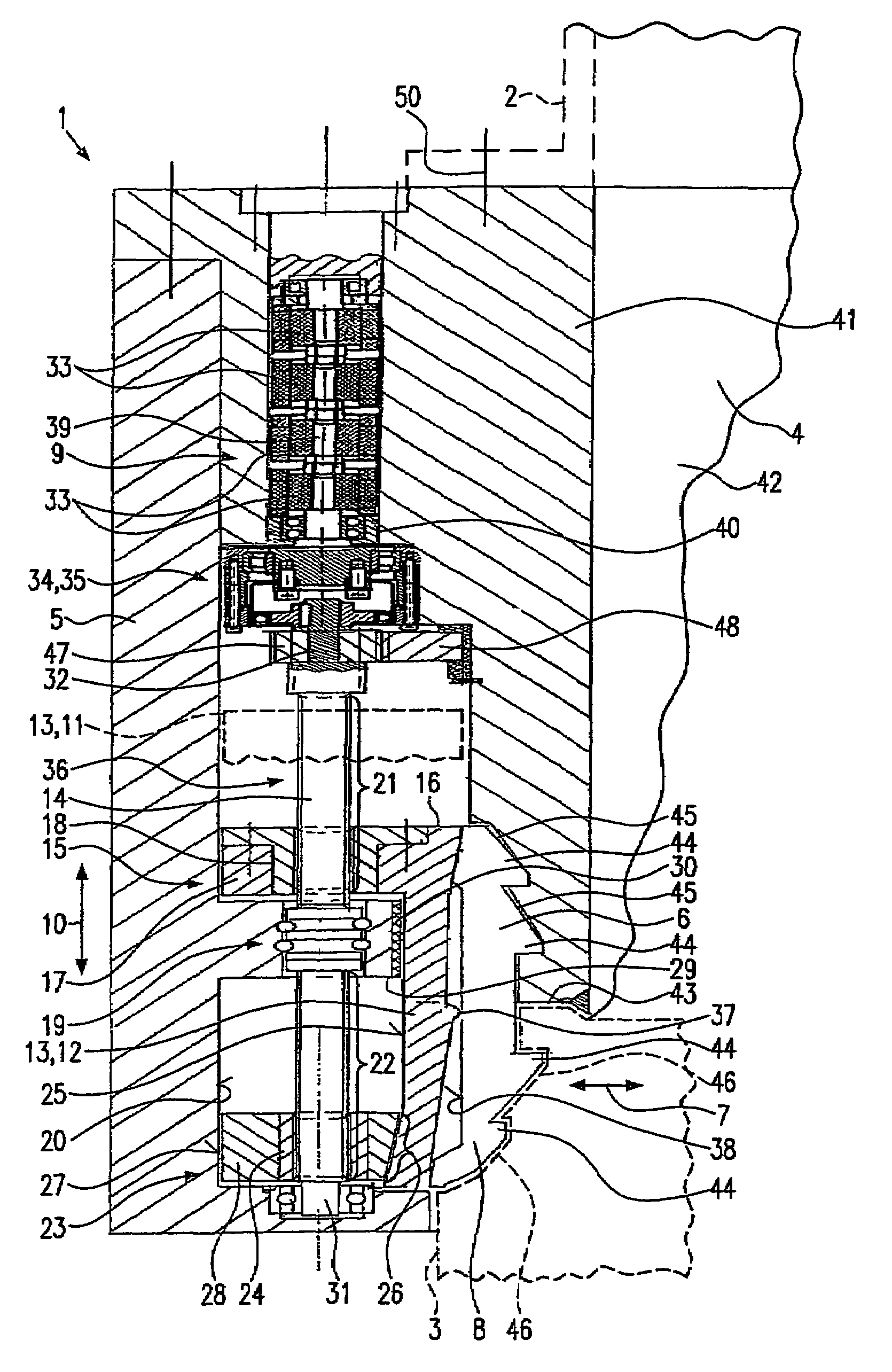
[0040]FIG. 1 is a lateral, perspective and partly cut view of a known connection device 1. Said device comprises an outer housing 5 of an essentially cylindrical form. An inner housing 41 is arranged within the outer housing 5. At the end of the inner housing that is the upper one in FIG. 1, a plurality of screw bolts 50 are provided for securing a tubular member. The tubular member is detachably secured by means of the screw bolts to the inner housing 41 and is in communication with a corresponding central inner bore of the inner housing 41. Inner housing 41 and outer housing 5 have arranged thereinbetween a clamp ring 6 which in its lower portion comprises a plurality of clamping fingers 8. Said fingers are elastically deflectable in radial direction. Clamp ring 6 and outer housing 5 have arranged thereinbetween a deflecting bushing 13 displaceable in axial direction of the connection device 1 by means of at least one driving means 9. The driving means 9 is formed by at least one ...


PUM


Abstract

A connection device for connecting a tubular member to another member comprises a clamp ring, which is arranged in an inner bore of an outer housing, and includes a plurality of clamping fingers which are deflectable essentially in radial direction relative to the inner bore and a deflecting bushing which is displaceable by at least one driving means in axial direction of the inner bore between a stand-by position and a deflecting position. The deflecting bushing in its deflecting position deflects the clamping fingers radially inwardly. The driving means comprises a rotatable, axially not displaceable spindle along which the deflecting bushing is movable.

Description

CROSS-REFERENCE TO RELATED APPLICATIONS[0001]This application is a National Phase entry of PCT Application No. PCT / EP2003 / 009700 filed 1 Sep. 2003 which claims priority to German Application No. 202 13 393.1 filed 30 Aug. 2002; both of which are incorporated herein by reference. This application is related to the following applications: PCT Application No. PCT / EP2003 / 009701 filed 1 Sep. 2003 which claims priority to German Application No. 202 13 391.5 filed 30 Aug. 2003; PCT Application No. PCT / EP2003 / 009698 filed 1 Sep. 2003 which claims priority to German Application No. 202 13 365.6 filed 30 Aug. 2002; PCT Application No. PCT / EP2003 / 009697 filed 1 Sep. 2003 which claims priority to German Application No. 202 13 389.3 filed 30 Aug. 2002; PCT Application No. PCT / EP2003 / 009696 filed 1 Sep. 2003 which claims priority to German Application No. 202 13 364.8 filed 30 Aug. 2002; PCT Application No. PCT / EP2003 / 009699 filed 1 Sep. 2003 which claims priority to German Application No. 202 13...

Claims


Application Information

Patent Timeline
Patent Type & Authority Patents(United States)
IPC IPC(8): F16L35/00E21B33/038
CPCE21B33/038Y10S285/92
Inventor BIESTER, KLAUS
Owner ONESUBSEA IP UK LTD
Why Eureka
Try Eureka