Pipe coupling

a technology of couplings and pipes, applied in the direction of sleeve/socket joints, joints with sealing surfaces, fluid pressure sealed joints, etc., can solve the problems of user frustration, couplings are not reusable, and the user needs to handle a number

Inactive Publication Date: 2008-12-30
CAMBRIDGE BRASS
View PDF6 Cites 35 Cited by
  • Summary
  • Abstract
  • Description
  • Claims
  • Application Information

AI Technical Summary

Problems solved by technology

However, where excessive exterior pressure on the pipe would result in the pipe collapsing such that the pipe is damaged and / or the seals or camming or gripping means fails, internal support is typically provided in the form of a tubular insert either in plastic or stainless steel.
One difficulty with such couplings is the need for the user to handle a number of small elements (typically the seals, and camming and gripping elements) during installation.
This can result in frustration on the part of the user while he fumbles with the various parts to ensure that they are installed in the correct order and orientation.
If the user fails to install these parts in the correct order and orientation, the connection can fail resulting in leakage.
This disadvantage is particularly acute where installation takes place in difficult conditions, for example where the fitting is located in an awkward location, or where the installation is taking place on waterworks, often with the user standing in a wet and muddy hole where fingers are slippery and where a dropped part is irretrievably lost.
Further, the camming or gripping means typically used on the exterior of the pipe can often result in an excessive localization of forces that may result in damage and / or collapse of the pipe that can result in failure.
Additionally, most present couplings are not reusable since the camming or gripping means used are permanently deformed during use.
Finally, with most present couplings the coupling can easily be under-tightened or over-tightened onto the pipe and / or the fitting, which may result in damage to the pipe, to the fitting or to the coupling and may also result in failure of the coupling.

Method used


Image

  • Pipe coupling
  • Pipe coupling
  • Pipe coupling

Examples


Embodiment Construction

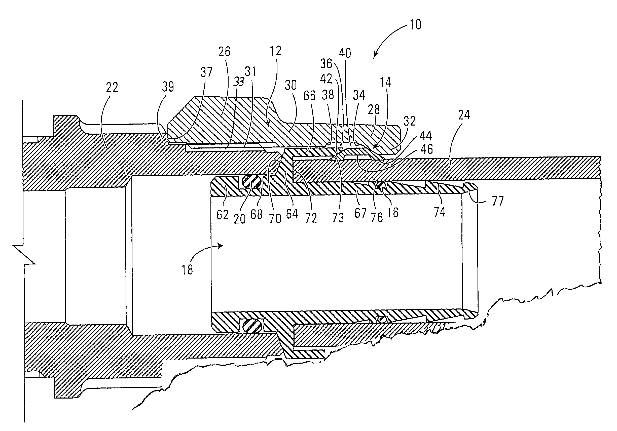
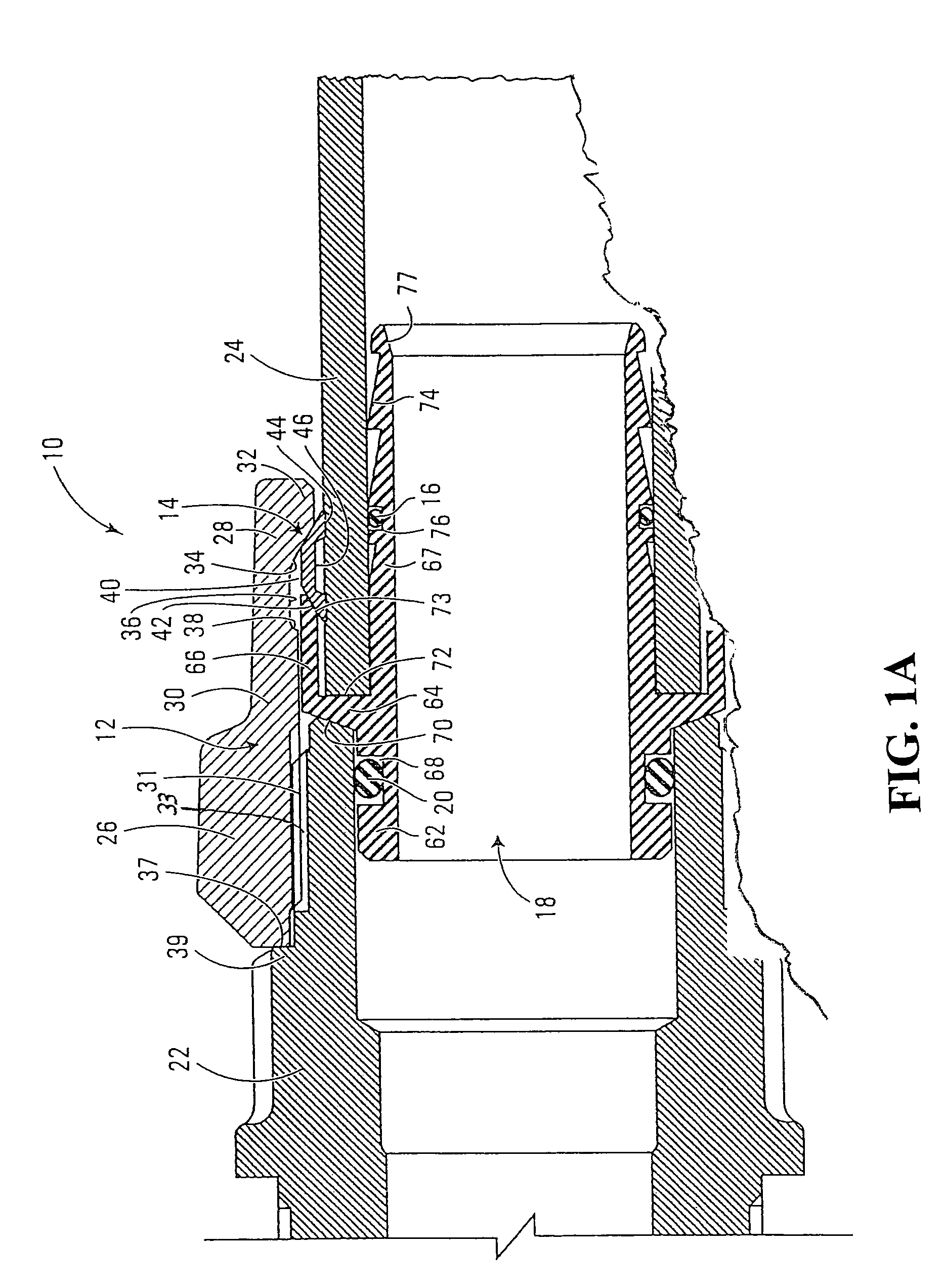
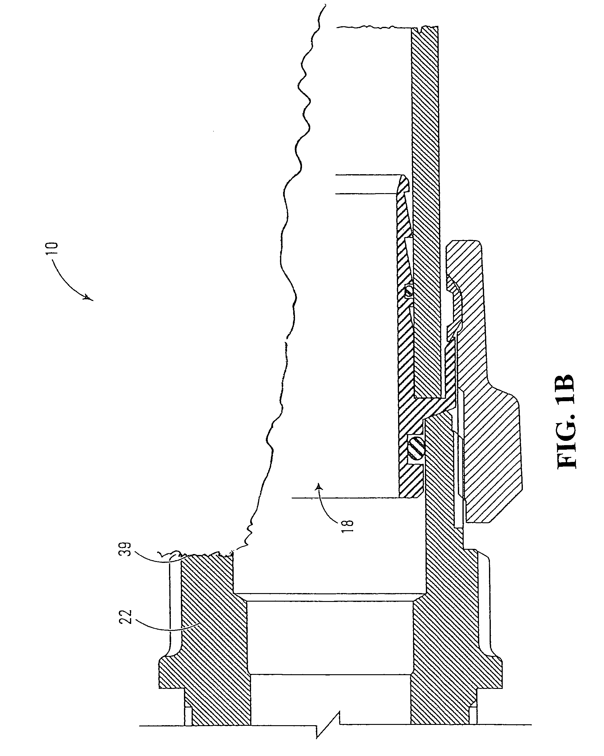
[0059]A preferred embodiment of the coupling of the present invention is shown in the attached drawings. In the exemplary application illustrated, the coupling is used to connect a polyethylene pipe to a cast brass alloy fitting stub in a waterworks application. The coupling is located between the pipe and the stub.

[0060]In this description and in the claims, the terms “axial” and “axially” are used to describe a direction parallel to a centerline of the pipe once the coupling is installed, while “radial” and “radially” are used to describe a direction perpendicular to and extending from the centerline of the pipe once the coupling is installed. Further, “forward” is used to describe features which are located nearer the fitting stub and away from the pipe once the coupling is installed, while “rearward” is used to describe features which are located nearer the extended pipe and away from the fitting stub once the coupling is installed.

[0061]FIG. 1A is a cross-sectional view of the ...


PUM

PropertyMeasurementUnit
angleaaaaaaaaaa
angleaaaaaaaaaa
pressureaaaaaaaaaa

Abstract

A coupling for creating a fluid-conducting connection between a pipe and a stub, where the stub has no pipe-supporting extension over which the pipe is to be connected. The coupling includes a coupling body having a forward end for being secured to the stub, a rearward end for receiving the pipe, and an internal bore therethrough; stub connection for securing the forward end of the coupling body to the stub; a pipe support for providing internal support for an end section of the pipe being engaged by the coupling; gripper engaging means for causing the gripper to grip the pipe; a seal between the stub and the pipe; and a gripper located within the internal bore of the coupling body, the gripper and the coupling body configured to engage the pipe with the gripper when the stub is secured in the stub connection.

Description

FIELD OF THE INVENTION[0001]The invention relates to pipe couplings, and in particular to couplings used to connect pipes to fittings such as valves and adapters.BACKGROUND OF THE INVENTION[0002]Particularly in the plumbing and waterworks industries, situations frequently arise during installation or repair of piping where it is necessary to connect pipes to various fittings such as corporation valves, curb valves and various adapters. These situations can arise for example during water service line installation or repair. Such piping can include service tubes and may be made of polyethylene pipe / tubing for example.[0003]Typically, such fittings are provided with a stub, usually externally threaded, for receiving a sealed fluid-communicating connection with the pipe. The threading on such stubs is typically of an industry standard such as corporation fitting thread, to allow standard threaded couplings to be mounted thereon.[0004]Such pipe-fitting couplings typically come in two mai...

Claims


Application Information

Patent Timeline
Patent Type & Authority Patents(United States)
IPC IPC(8): F16L33/00F16L19/02F16L19/06F16L19/08F16L21/02F16L21/04F16L21/06F16L33/22F16L47/00F16L47/06
CPCF16L19/0206F16L19/061F16L19/10F16L19/08F16L33/224
Inventor NORMAN, JAMIE
Owner CAMBRIDGE BRASS
Why Eureka
Try Eureka