Muff coupling for vehicle couplers

a technology for couplings and vehicle couplers, applied in the direction of sleeve/socket joints, mechanical equipment, transportation and packaging, etc., can solve the problems of unsatisfactory couplings, unsatisfactory couplings, and large weight of couplings,

Active Publication Date: 2008-12-30
DELLNER COUPLERS AB
View PDF12 Cites 25 Cited by
  • Summary
  • Abstract
  • Description
  • Claims
  • Application Information

AI Technical Summary

Benefits of technology

[0007]The present invention aims at obviating the above-mentioned disadvantages of previously known muff couplings for vehicle couplers and at providing an improved muff coupling. Therefore, a primary object of the invention is to provide a muff coupling that is light and formed for transferring occurring dynamic forces in a strength-wise expedient train of forces from one component to the other. It is also an object to provide possibilities for, if required, increasing the active area of the contact surfaces via which transfer of force takes place, with the outmost object of improving the strength and reliability of the muff coupling. In a particular aspect, the invention aims at providing a muff coupling that in a universal way enables coupling of not only components having one and the same type of connecting flanges, but also components having end flanges of different types. It is also an object to provide a muff coupling that is easy to handle in connection with repairs and maintenance.

Problems solved by technology

Previously known muff couplings for rail vehicle couplers are, however, associated with annoying disadvantages.
One such disadvantage is that the couplings have a considerable weight and are ungainly.
In spite of the muff and the bulges thereof as well as the end flanges on the coupled components co-operating with the same being strong and weight-swallowing, the capacity of the established coupling joint to transfer the dynamic forces in a train of forces from one component to the other is, however, not optimal.
A particularly annoying consequence of the structurally strong embodiment of the muff couplings is that they are weight-swallowing so far that each kilogram of extra weight reduces net loading capacity of the vehicles correspondingly.

Method used


Image

  • Muff coupling for vehicle couplers
  • Muff coupling for vehicle couplers
  • Muff coupling for vehicle couplers

Examples


Embodiment Construction

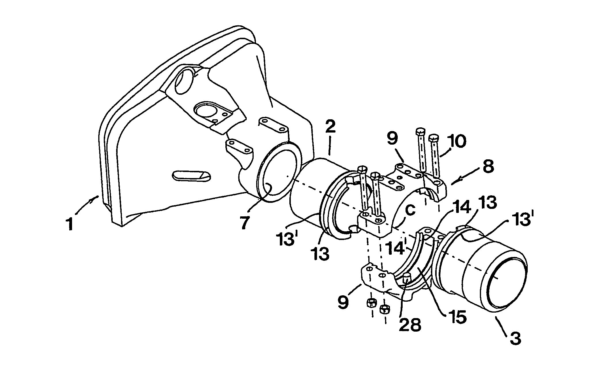
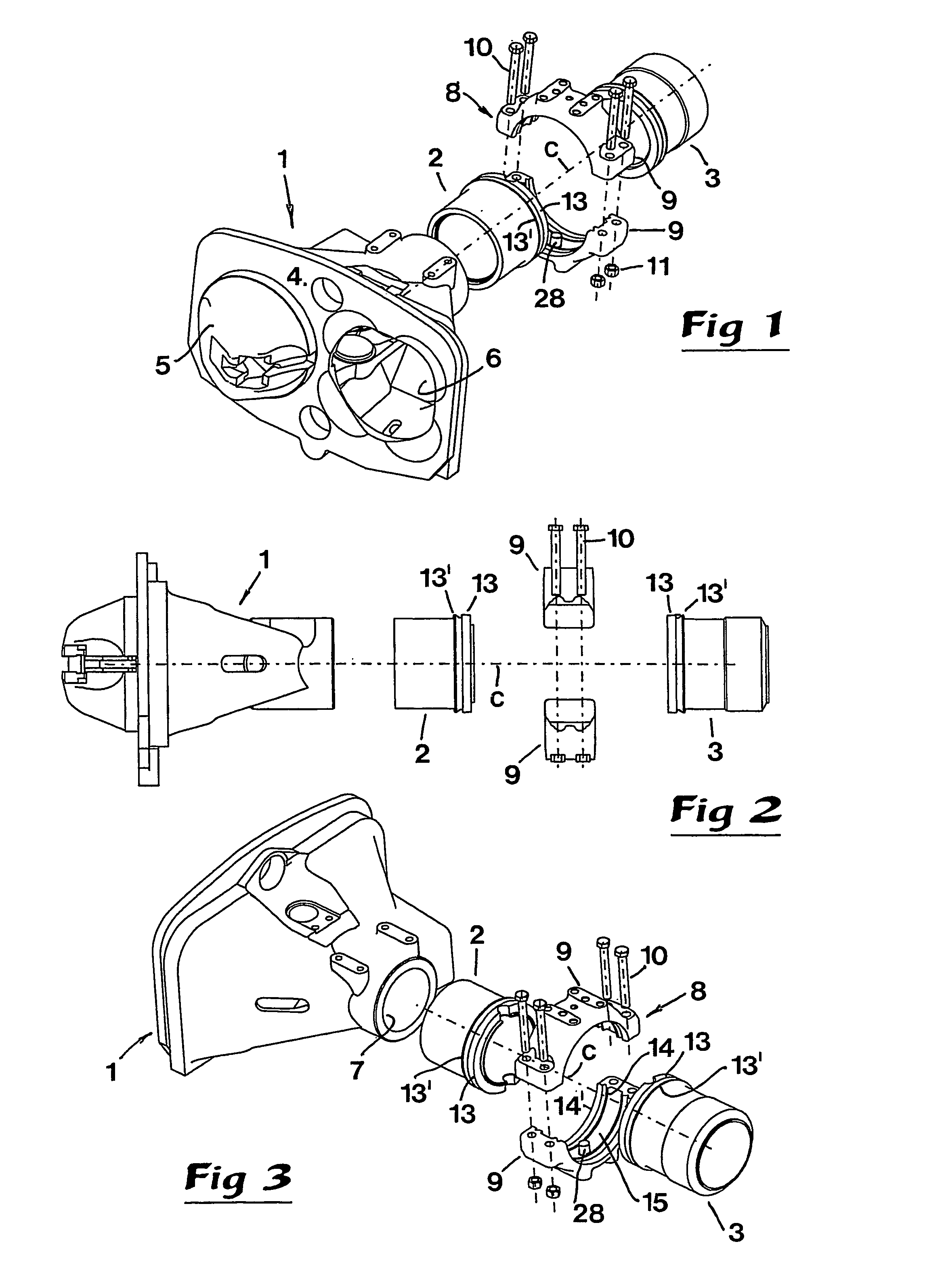
[0022]In FIGS. 1-3, an individual coupler is visualised, which includes a front, house-like head 1, as well as two part components 2, 3 that in the composed state of the coupler are connected mutually—as well as with the head 1. In the example in question, the coupler consists of an automatic coupler, the head of which on the front side 4 thereof is formed with a male-like projection 5, as well as a female-like seating 6, in the house a ratchet mechanism being built-in that enables coupling of the coupler with a compatible coupler on a nearby carriage, more precisely by the male element 5 being inserted into a corresponding seating 6 in the co-operating coupler (and vice versa). In the back side of the head 1, a circular opening 7 is formed to which the component 2 may be connected and fixed. In the example, the component 2 consists of a distance tube or extension tube, the main function of which is to finally decide the total length of the finished coupler. The tube 2 has a rotatio...


PUM


Abstract

A muff coupling intended for vehicle couplers includes two components formed with ring-shaped flanges, as well as a muff consisting of at least two arch parts tightenable against each other, each having an inner flute formed between two inwardly turned bulges, which flute is delimited by obliquely inclined side surfaces to, upon radial tightening of the arch parts against each other, be pressed against analogously obliquely inclined shoulder surfaces on the flanges and thereby, by wedge action, transfer axial component forces to the same, pressing the ends of the components in close contact against each other. The arch parts are formed with double sets of bulges for cooperation with double flanges on the respective component, whereby forces that are transferred between the components via the muff are distributed to a plurality of axially spaced-apart pairs of contact surfaces in an axial train of forces near the outside of the components.

Description

TECHNICAL FIELD OF THE INVENTION[0001]This invention relates to a muff coupling intended for vehicle couplers of the type that comprises two components, formed with ring-shaped flanges, and interconnectable via a muff comprising of at least two arch parts tightenable against each other, each of which separately has an inner flute formed between two inwardly turned bulges, which flute is delimited by a bottom and two opposite, force-transferring side surfaces, which are obliquely inclined in order to, upon radial tightening of the arch parts against each other, be pressed against analogously obliquely inclined shoulder surfaces on the flanges of the components and thereby, by wedge action, transfer axial component forces to the same with the purpose of pressing the ends of the components in close contact against each other.BACKGROUND OF THE INVENTION[0002]Couplers having muff couplings of the kind generally mentioned above are used above all for the coupling of rail-mounted vehicles ...

Claims


Application Information

Patent Timeline
Patent Type & Authority Patents(United States)
IPC IPC(8): F16L23/00B61G7/00B61G9/20
CPCB61G7/00B61G9/20
Inventor WESTMAN, ANDERSJERNBERG, GUNNARERIKSSON, MATS
Owner DELLNER COUPLERS AB
Why Eureka
Try Eureka